
Precision in Motion: Unveiling the Secrets of Load Cell Mastery
Load cells are the unsung heroes behind accurate weight and force measurements in various industries. These small devices play a crucial role in ensuring precision and reliability. From monitoring product quality to optimizing performance, load cells provide the critical data needed for success. In this guide, we'll explore the essential characteristics of load cells, including accuracy, linearity, and sensitivity, unraveling their significance and impact on your measurements. Get ready to dive into the world of load cell technology and unlock the key to unparalleled measurement accuracy!
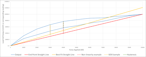
Fig 1. Load Cell Characteristics expressed via an expanded view in Excel. Typically, the BFSL does not start at zero.
What does "Load cell characteristic" mean?
A load cell characteristic refers to the specific properties and features of a load cell, which is a type of transducer used to measure force or weight. Load cells are commonly used in various applications such as industrial weighing systems, tension monitoring, and material testing.
The characteristic of a load cell includes several important parameters and specifications that define its performance and capabilities. Some key characteristics of a load cell are:
- Sensitivity: It indicates the relationship between the output signal of the load cell and the applied force or weight. It is typically expressed as the output voltage or current per unit of applied force.
- Accuracy: This refers to how closely the load cell measures the actual force or weight. It is usually specified as a percentage of the full-scale output or as a percentage of the applied force.
- Linearity: It represents how well the load cell's output signal follows a straight line in relation to the applied force. A highly linear load cell will provide a proportional output for different force levels.
- Overload Capacity: This indicates the maximum force or weight that the load cell can withstand without sustaining permanent damage or affecting its performance.
- Temperature Compensation: Load cells are sensitive to temperature variations, and temperature compensation ensures that the measurements remain accurate across a range of temperatures.
- Environmental Protection: Load cells may have different levels of protection against moisture, dust, and other environmental factors. It is usually specified using an IP (Ingress Protection) rating.
- Output Signal: Load cells can provide various types of output signals, such as analog voltage, current, or digital signals like RS-485 or Ethernet, depending on the application and system requirements.
Understanding the load cell characteristic is crucial when selecting the right load cell for a specific application, as it determines the accuracy, reliability, and compatibility of the load cell within the intended system.
Load cell sensitivity
Load cell sensitivity refers to the relationship between the output signal of a load cell and the applied force or weight. It quantifies how much the load cell's output signal changes in response to a given change in applied force.
Sensitivity is typically expressed as the output signal per unit of applied force, such as millivolts per volt (mV/V) or milliamperes per volt (mA/V). For example, a load cell with a sensitivity of 2 mV/V means that for every volt of excitation voltage applied to the load cell, the output signal will change by 2 millivolts for every unit of force or weight applied.
The sensitivity of a load cell is a crucial parameter as it determines the resolution and accuracy of the measurements. A higher sensitivity means that the load cell can detect smaller changes in force or weight, providing more precise measurements. On the other hand, a lower sensitivity may result in less precise measurements, requiring larger force or weight changes to produce noticeable changes in the output signal.
It's important to note that load cell sensitivity is specified under certain conditions, such as the load cell being properly calibrated and used within its rated capacity range. Factors like temperature variations, mechanical stress, and environmental conditions can affect the sensitivity of a load cell, so it's essential to consider these factors during the application and use of the load cell.
When selecting a load cell for a specific application, it's crucial to consider the required sensitivity based on the level of precision needed and the anticipated range of forces or weights to be measured. Different applications may have different sensitivity requirements, and choosing a load cell with an appropriate sensitivity ensures accurate and reliable measurements in the intended system.
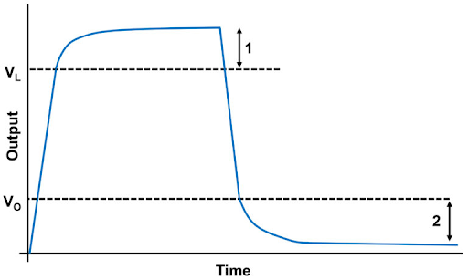
Fig 2. Load Cell Creep
How can measure the Load cell sensitivity?
To measure the sensitivity of a load cell, you will need a few tools and equipment. Here is a step-by-step guide on how to measure load cell sensitivity:
- Setup: Ensure that the load cell is properly installed and connected to a suitable measuring instrument or data acquisition system. Follow the manufacturer's guidelines for the correct wiring and setup.
- Excitation Voltage: Apply the recommended excitation voltage to the load cell. This voltage is specified by the load cell manufacturer and can typically be found in the load cell's datasheet or technical documentation.
- Zero Calibration: Perform a zero calibration by applying no load to the load cell and adjusting the output signal to zero using the appropriate calibration or zero adjustment mechanism provided by the load cell or measuring instrument.
- Calibration Weights: Obtain a set of known calibration weights that cover the desired range of forces or weights you want to measure. These weights should be calibrated and have traceable accuracy.
- Incremental Load Application: Start with the lowest calibration weight and apply it to the load cell. Allow the load cell output signal to stabilize and record the corresponding output reading. Repeat this step for each incremental weight in the set.
- Output Measurement: Measure and record the load cell's output signal (voltage, current, or digital value) for each applied weight. Ensure that the measurements are stable and repeatable before recording.
- Data Analysis: Plot a calibration curve or graph that represents the load cell's output readings against the applied weights. The graph should indicate a linear relationship between the load cell's output signal and the applied force or weight.
- Sensitivity Calculation: Calculate the sensitivity of the load cell by determining the slope of the calibration curve. The sensitivity is the change in the output signal (e.g., voltage or current) per unit change in applied force or weight.Sensitivity = ΔOutput / ΔForce or WeightHere, ΔOutput represents the change in the load cell's output signal, and ΔForce or Weight represents the corresponding change in applied force or weight.
- Unit Conversion: If necessary, convert the sensitivity value to the desired units based on the load cell's specifications and the measurement requirements. For example, if the sensitivity is expressed in millivolts per volt (mV/V), you may need to convert it to pounds per volt (lb/V) or Newtons per volt (N/V).
It's important to note that load cell sensitivity may vary with environmental factors, such as temperature, so it's recommended to perform sensitivity measurements under controlled conditions or apply temperature compensation techniques if necessary.
Always refer to the load cell manufacturer's documentation and guidelines for specific instructions on sensitivity measurement, as different load cells may have slightly different procedures or requirements.
Load Cell Sensitivity formula
The formula for calculating load cell sensitivity is as follows:
Sensitivity = ΔOutput / ΔForce or Weight
In this formula:
- ΔOutput represents the change in the load cell's output signal (such as voltage, current, or digital value).
- ΔForce or Weight represents the corresponding change in the applied force or weight.
The sensitivity of a load cell quantifies the relationship between the change in its output signal and the corresponding change in the applied force or weight. It indicates how much the load cell's output signal varies per unit change in the applied force or weight. The sensitivity is often expressed in units of output per unit force or weight (e.g., mV/V, N/V, or lb/V).
To calculate the sensitivity, measure the change in the load cell's output signal for a known increment of force or weight and divide it by the corresponding change in force or weight. This provides a ratio that represents the load cell's sensitivity in the given units.
It's important to note that sensitivity may vary with different load cell models and designs. Therefore, it's essential to consult the load cell manufacturer's documentation for specific instructions on measuring and interpreting sensitivity, as well as any unit conversions or calibration considerations that may apply.
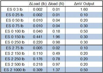
Fig 3. Load cell sensitivity
Load cell accuracy
Load cell accuracy refers to the degree of conformity between the measured output of a load cell and the actual value of the applied force or weight. It represents how closely the load cell can provide measurements that are free from systematic errors or deviations.
Accuracy is typically specified as a percentage of the full-scale output (FSO) or as a percentage of the applied force or weight. For example, a load cell with an accuracy of ±0.1% FSO means that the measured output can deviate by a maximum of 0.1% of the load cell's full-scale output.
Several factors contribute to the accuracy of a load cell:
- Linearity: Linearity refers to the ability of the load cell to provide a linear output response over the entire range of applied forces or weights. A highly linear load cell will accurately translate different force levels into proportional output signals.
- Hysteresis: Hysteresis is the difference in load cell output when the same force is applied successively in increasing and decreasing order. An accurate load cell should exhibit minimal hysteresis to ensure consistent measurements.
- Nonlinearity: Nonlinearity refers to the deviation from a straight-line response of the load cell's output over the applied force or weight range. A load cell with low nonlinearity will provide more accurate measurements.
- Repeatability: Repeatability represents the load cell's ability to provide consistent output readings when the same force or weight is applied repeatedly under the same conditions. A high level of repeatability contributes to measurement accuracy.
- Temperature Effects: Load cells can be affected by temperature variations, leading to changes in their output signals. Temperature compensation techniques are employed to minimize these effects and maintain accuracy across a range of temperatures.
- Calibration: Proper calibration of a load cell is essential to achieve accurate measurements. Calibration involves comparing the load cell's output to known standard forces or weights and adjusting any discrepancies.
When selecting a load cell for a specific application, it is important to consider the required accuracy based on the level of precision needed. Higher accuracy load cells are generally more expensive, so it is important to strike a balance between the required accuracy and the associated cost. Additionally, environmental conditions, mechanical stress, and proper installation and usage practices can impact the accuracy of a load cell, so these factors should be taken into account to maintain optimal performance.
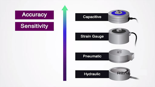
Fig 4. Load cell accuracy and sensitivity comparision
How can measure the Load cell accuracy?
Measuring the accuracy of a load cell involves comparing its output readings to a known reference or standard. Here's a step-by-step guide on how to measure load cell accuracy:
- Setup: Ensure that the load cell is properly installed and connected to a suitable measuring instrument or data acquisition system. Follow the manufacturer's guidelines for the correct wiring and setup.
- Excitation Voltage: Apply the recommended excitation voltage to the load cell. This voltage is specified by the load cell manufacturer and can typically be found in the load cell's datasheet or technical documentation.
- Zero Calibration: Perform a zero calibration by applying no load to the load cell and adjusting the output signal to zero using the appropriate calibration or zero adjustment mechanism provided by the load cell or measuring instrument.
- Reference Standard: Obtain a known reference standard for the force or weight you wish to measure. The reference standard should have a traceable accuracy and be calibrated within the desired range of measurement.
- Incremental Load Application: Apply the reference standard to the load cell and allow the load cell output signal to stabilize. Record the corresponding output reading for each applied load.
- Repeat Measurements: Repeat the load application and output measurement process multiple times to ensure repeatability and verify consistent results.
- Data Analysis: Compare the load cell's output readings to the known reference standard values. Calculate the difference or error between the load cell's readings and the reference values for each applied load.
- Accuracy Calculation: Calculate the load cell accuracy using the obtained error values. The accuracy is typically expressed as a percentage of the full-scale output (FSO) or as a percentage of the applied load.Accuracy = (|Measured Value - Reference Value| / Reference Value) x 100Here, |Measured Value - Reference Value| represents the absolute difference between the load cell's measured value and the reference value.
- Data Evaluation: Analyze the accuracy results to determine if they meet the required specifications or standards for your application. Consider factors such as measurement uncertainty, acceptable error limits, and the load cell's intended use.
- Calibration and Adjustment: If the load cell's accuracy is outside the acceptable range, calibration and adjustment may be required. Consult the load cell manufacturer's guidelines or seek assistance from a qualified technician or calibration service to perform necessary adjustments.
It's important to note that load cell accuracy may be influenced by various factors, including temperature variations, environmental conditions, and the load cell's age or condition. Therefore, it's recommended to perform accurate measurements periodically and under controlled conditions to maintain reliable and accurate measurements.
Always refer to the load cell manufacturer's documentation and guidelines for specific instructions on accurate measurement and calibration procedures, as different load cells may have slightly different requirements and procedures.
Load Cell Accuracy formula
The formula for calculating load cell accuracy is as follows:
Accuracy = (|Measured Value - Reference Value| / Reference Value) x 100
In this formula:
- Measured Value refers to the output reading or measurement obtained from the load cell.
- Reference Value represents the known reference or standard value for the force or weight being measured.
- |...| denotes the absolute value of the difference between the measured value and the reference value.
- The formula calculates the percentage difference between the measured value and the reference value.
By applying this formula, you can determine the accuracy of the load cell by quantifying the percentage deviation between its output readings and the known reference values.
Load cell linearity
Load cell linearity refers to the degree to which the relationship between the applied force or weight and the load cell's output signal follows a straight line. It indicates how accurately the load cell converts different force levels into proportional output readings.
Ideally, a load cell should exhibit perfect linearity, meaning that its output would increase or decrease in direct proportion to the applied force or weight. However, in practice, load cells may have some degree of nonlinearity due to various factors, including manufacturing tolerances, mechanical properties, and electronic components.
Nonlinearity in load cells can manifest in two ways:
- Zero-Point Nonlinearity: Zero-point nonlinearity refers to the deviation from the expected output signal when no force or weight is applied to the load cell. It represents the offset or discrepancy in the load cell's output at zero loads. Zero-point nonlinearity is typically specified as a percentage of the full-scale output (FSO).
- Full-Scale Nonlinearity: Full-scale nonlinearity refers to the deviation from a straight line response throughout the load cell's entire measurement range, from zero loads to its maximum rated capacity. Full-scale nonlinearity is also specified as a percentage of the FSO.
Load cell linearity is commonly represented graphically using a calibration curve or a linearity plot. The calibration curve displays the load cell's actual output readings against the applied forces or weights. The closer the calibration curve aligns with a straight line, the higher the linearity of the load cell.
To ensure accurate measurements, load cell manufacturers often perform calibration procedures to determine the linearity characteristics and establish correction factors or algorithms. These calibration techniques help compensate for nonlinearity and improve the load cell's overall accuracy.
When selecting a load cell for a specific application, it is important to consider the required level of linearity based on the desired measurement accuracy. Highly linear load cells are preferred when precise measurements are essential, such as in laboratory testing or quality control applications. However, it's important to note that higher linearity may come at a higher cost, so the specific application requirements and budget constraints should be considered when choosing a load cell.
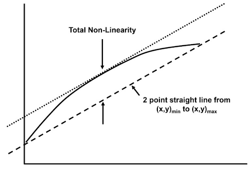
Fig 5. Non-Linearity with Baseline
How can measure the Load cell linearity?
To measure the linearity of a load cell, you will need a known reference standard and a data acquisition system or measuring instrument capable of recording the load cell's output readings. Here's a step-by-step guide on how to measure load cell linearity:
- Setup: Ensure that the load cell is properly installed and connected to the measuring instrument or data acquisition system. Follow the manufacturer's guidelines for the correct wiring and setup.
- Excitation Voltage: Apply the recommended excitation voltage to the load cell. This voltage is specified by the load cell manufacturer and can typically be found in the load cell's datasheet or technical documentation.
- Zero Calibration: Perform a zero calibration by applying no load to the load cell and adjusting the output signal to zero using the appropriate calibration or zero adjustment mechanism provided by the load cell or measuring instrument.
- Reference Standard: Obtain a known reference standard for the force or weight you wish to measure. The reference standard should have a traceable accuracy and cover the desired range of measurement.
- Incremental Load Application: Apply the reference standard to the load cell in a series of incremental steps. Start with the lowest reference load and gradually increase the load in equal intervals or steps.
- Output Measurement: For each applied load, record the load cell's output reading using the data acquisition system or measuring instrument. Ensure that the measurements are stable and repeatable before recording.
- Data Analysis: Plot a graph or calibration curve that represents the load cell's output readings against the applied loads. The graph should indicate the relationship between the load cell's output signal and the applied force or weight.
- Linearity Calculation: Calculate the linearity of the load cell by determining the deviation or error between the load cell's output readings and the ideal linear relationship. This is typically done by measuring the maximum deviation from a straight line fitted to the calibration curve.Linearity = (|Measured Value - Ideal Value| / Full-Scale Output) x 100Here, |Measured Value - Ideal Value| represents the absolute difference between the load cell's measured value and the corresponding ideal value on the linear fit line.
- Data Evaluation: Analyze the linearity results to determine if they meet the required specifications or standards for your application. Consider factors such as acceptable error limits, the load cell's intended use, and the linear fit criteria.
- Calibration and Adjustment: If the load cell's linearity is outside the acceptable range, calibration and adjustment may be required. Consult the load cell manufacturer's guidelines or seek assistance from a qualified technician or calibration service to perform necessary adjustments.
It's important to note that load cell linearity measurements may be influenced by various factors, including environmental conditions, load cell mounting, and the load cell's age or condition. Therefore, it's recommended to perform linearity measurements periodically and under controlled conditions to maintain accurate and reliable measurements.
Always refer to the load cell manufacturer's documentation and guidelines for specific instructions on linearity measurement and calibration procedures, as different load cells may have slightly different requirements and procedures.
Load Cell linearity formula
The formula for calculating load cell linearity is as follows:
Linearity = (|Measured Value - Ideal Value| / Full-Scale Output) x 100
In this formula:
- Measured Value refers to the output reading or measurement obtained from the load cell.
- Ideal Value represents the expected or ideal output value based on a linear relationship with the applied force or weight.
- Full-Scale Output denotes the maximum output value that the load cell can produce.
- |...| denotes the absolute value of the difference between the measured value and the ideal value.
- The formula calculates the percentage deviation between the measured value and the ideal value relative to the full-scale output.
By applying this formula, you can assess the linearity of the load cell by quantifying the percentage deviation between its output readings and the ideal values expected in a linear relationship. This helps evaluate how closely the load cell adheres to a linear response across its operating range.
Formulas table
Table 1. Formulas table
| Measurement | Formula |
| Load Cell Accuracy | Accuracy = (|Measured Value - Reference Value| / Reference Value) x 100 |
| Load Cell Linearity | Linearity = (|Measured Value - Ideal Value| / Full-Scale Output) x 100 |
| Load Cell Sensitivity | Sensitivity = ΔOutput / ΔForce or Weight |
Please note that the formulas mentioned here are general representations and may need to be adjusted based on the specific units and conventions used in your measurement system. Additionally, the "Measured Value," "Reference Value," "Ideal Value," "Full-Scale Output," "ΔOutput," and "ΔForce or Weight" terms in the formulas should be replaced with the actual values and units relevant to your load cell and measurement setup.
Examples using these formulas
Example 1: Load Cell Accuracy Suppose you have a load cell that is measuring a weight and the reference value for that weight is 100 kg. The load cell provides a measured value of 98 kg. Using the accuracy formula, we can calculate the accuracy:
Accuracy = (|Measured Value - Reference Value| / Reference Value) x 100 Accuracy = (|98 kg - 100 kg| / 100 kg) x 100 Accuracy = 2%
Therefore, the load cell has an accuracy of 2%, indicating that the measured value deviates by 2% from the reference value.
Example 2: Load Cell Linearity Let's assume you have a load cell with a full-scale output of 1000 N. You perform a calibration test by applying forces of 200 N, 400 N, 600 N, 800 N, and 1000 N, and record the corresponding measured values. The ideal values on a linear fit line for these forces are 200 N, 400 N, 600 N, 800 N, and 1000 N. Using the linearity formula, we can calculate the linearity for one of the measured values:
Measured Value = 580 N Ideal Value = 600 N Full-Scale Output = 1000 N
Linearity = (|Measured Value - Ideal Value| / Full-Scale Output) x 100 Linearity = (|580 N - 600 N| / 1000 N) x 100 Linearity = 2%
Thus, the load cell exhibits linearity of 2% at a measured value of 580 N, indicating a 2% deviation from the ideal linear relationship.
Example 3: Load Cell Sensitivity Suppose you have a load cell that produces an output voltage change of 0.5 mV when an applied force of 10 kg is increased. Using the sensitivity formula, we can calculate the sensitivity:
ΔOutput = 0.5 mV ΔForce = 10 kg
Sensitivity = ΔOutput / ΔForce Sensitivity = 0.5 mV / 10 kg Sensitivity = 0.05 mV/kg
Hence, the load cell has a sensitivity of 0.05 mV/kg, indicating that the output voltage changes by 0.05 mV per kilogram increase in the applied force.
Please note that these examples are for illustration purposes, and actual load cell measurements may involve different units and values. It's crucial to refer to the load cell manufacturer's documentation and guidelines for specific instructions and units applicable to your load cell.
Load cell overload or over-capacity
Load cell overload capacity refers to the maximum force or weight that a load cell can withstand without sustaining permanent damage or significantly affecting its performance. It represents the load cell's ability to handle forces or weights that exceed its rated capacity for a short period.
Load cells are designed to operate within a specified range of forces or weights, known as the rated capacity. Exceeding this rated capacity can cause permanent deformation, reduced accuracy, or even structural failure of the load cell. The overload capacity is typically specified as a percentage of the load cell's rated capacity.
For example, if a load cell has a rated capacity of 1000 kg and an overload capacity of 150%, it means that the load cell can handle a maximum force of 1500 kg without permanent damage or significant performance degradation.
The overload capacity of a load cell is an important consideration in applications where occasional or accidental overloading may occur. It provides a safety margin for unexpected force or weight spikes, prevents premature failure, and protects the load cell from damage.
It's important to note that while a load cell may have an overload capacity, it is not intended for continuous operation at levels exceeding its rated capacity. Prolonged operation in the overload range can lead to accelerated wear and reduced reliability of the load cell.
When selecting a load cell for an application, it is crucial to consider the anticipated force or weight range and choose a load cell with an appropriate rated capacity and overload capacity. This ensures that the load cell can withstand occasional overloads while still providing accurate and reliable measurements.
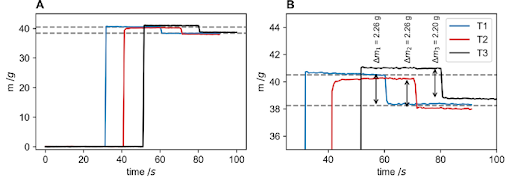
Fig 6. Repeat curves testing the sensitivity and precision of the load cell
Load cell Temperature Compensation
Load cell temperature compensation refers to the techniques and mechanisms employed to minimize the effects of temperature variations on the performance and accuracy of a load cell. Load cells are sensitive to temperature changes, and fluctuations in temperature can cause changes in their output readings, leading to measurement errors.
Temperature variations can affect load cells in several ways:
- Thermal Expansion: Load cells are typically made of materials that expand or contract with temperature changes. This can cause mechanical stress and strain in the load cell, resulting in output signal variations.
- Electrical Properties: Temperature can affect the electrical properties of the load cell, including the resistance and conductivity of the strain gauges or other sensing elements. These variations can impact the load cell's output signal.
- Zero Shift: Temperature changes can cause the load cell's zero point (output at zero loads) to shift, resulting in an offset in the measurements.
To compensate for these temperature effects, load cells incorporate temperature compensation techniques, which can be achieved in different ways:
- Zero Balancing: Load cells can be zero-balanced at the operating temperature to eliminate or minimize zero-shift errors. This involves adjusting the load cell's output when no force or weight is applied to align it with the desired zero point.
- Thermal Isolation: Load cells may employ thermal isolation techniques to minimize the transfer of heat from the surrounding environment to the load cell sensing elements. This helps reduce the impact of temperature variations on the load cell's performance.
- Thermally Stable Materials: Load cells can be manufactured using materials that have minimal thermal expansion properties to reduce mechanical stress and strain caused by temperature changes.
- Temperature Sensors: Load cells may integrate temperature sensors or compensate for temperature changes by measuring the ambient or load cell temperature and adjusting the output signal accordingly.
- Calibration: Load cells can be calibrated at different temperatures to establish temperature compensation algorithms or correction factors that can be applied to the measurements at different operating temperatures.
It's important to note that temperature compensation techniques can help reduce the impact of temperature variations on load cell measurements but cannot eliminate all temperature-related errors. Therefore, it's crucial to operate load cells within their specified temperature ranges and consider the application's temperature requirements when selecting and using load cells.
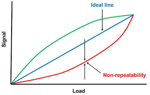
Fig 7. Non-repeatability
Load cell Environmental Protection
Load cell environmental protection refers to the measures taken to safeguard load cells from the potentially damaging effects of external environmental factors. Load cells are often used in various industrial and outdoor applications where they may be exposed to harsh conditions, such as moisture, dust, temperature extremes, and corrosive substances. Environmental protection ensures the load cell's longevity, reliability, and accurate performance in challenging environments.
Here are some common methods and features used for load cell environmental protection:
- Sealing: Load cells can be equipped with sealing mechanisms to prevent the ingress of moisture, dust, and other contaminants. Seals are typically applied to sensitive areas, such as cable entry points, connectors, and strain gauges.
- Hermetic Encapsulation: Some load cells employ hermetic encapsulation, which involves sealing the entire load cell in a protective enclosure to create a barrier against environmental elements. This approach provides high levels of protection against moisture, humidity, and corrosive substances.
- Protective Coatings: Load cells may feature specialized protective coatings or finishes to enhance their resistance to environmental factors. These coatings can provide additional protection against moisture, chemicals, and abrasion.
- IP Rating: Load cells are often assigned an Ingress Protection (IP) rating, which indicates the degree of protection against solid objects (first digit) and liquids (second digit). For example, an IP67-rated load cell is dust-tight and can withstand immersion in water up to a certain depth.
- Stainless Steel Construction: Load cells made from stainless steel are widely used due to their excellent corrosion resistance properties. Stainless steel load cells are more resistant to rust and chemical exposure, making them suitable for demanding environments.
- Temperature Tolerance: Load cells designed for extreme temperature environments may incorporate components and materials that can withstand a wide range of temperatures without affecting performance. This ensures reliable operation in both hot and cold environments.
- Environmental Testing: Load cells can undergo rigorous environmental testing to validate their performance under specific conditions, such as temperature cycling, humidity exposure, vibration, and shock. Testing ensures that load cells can withstand real-world environmental challenges.
The level of environmental protection required for a load cell depends on the application and the specific environmental conditions it will encounter. It's important to select load cells with adequate protection to ensure their longevity and accurate performance in the intended environment. Manufacturers often provide guidelines and specifications regarding the load cell's environmental protection capabilities to assist in selecting the appropriate load cell for specific applications.
Load cell output signal
The load cell output signal refers to the electrical signal generated by the load cell in response to an applied force or weight. Load cells are transducers that convert mechanical force or weight into an electrical signal that can be measured and processed by a data acquisition system or other devices.
The output signal of a load cell can be in various forms, depending on the load cell type and design. Here are the most common types of load cell output signals:
- Analog Voltage: Many load cells provide an analog voltage output. The output signal is usually proportional to the applied force or weight and typically ranges from 0 to a specified maximum voltage, such as 0 to 5 volts (V) or 0 to 10V.
- Analog Current: Some load cells generate an analog current output signal. The current output is typically proportional to the applied force or weight and may range from 4-20 milliamperes (mA) or 0-20 mA.
- Digital: Load cells with digital output signals to convert the measured force or weight into a digital format, which can be easily interfaced with digital systems or data acquisition devices. Common digital output formats include RS-485, Ethernet, or fieldbus protocols like CANopen or Modbus.
- Frequency: Certain load cells produce an output signal in the form of a frequency that varies with the applied force or weight. The frequency can be measured and used to determine the force or weight.
The output signal of a load cell is typically obtained by connecting the load cell to appropriate signal conditioning or amplification circuitry. This circuitry processes the small electrical signals generated by the load cell and amplifies or converts them into a more usable form for further analysis, recording, or control purposes.
It's important to note that the load cell output signal requires proper calibration and scaling to ensure accurate measurements. Calibration involves comparing the load cell's output to known forces or weights and adjusting the output signal accordingly. Scaling involves converting the raw output signal into meaningful units of force or weight based on the load cell's specifications and calibration.
Understanding the load cell's output signal type and characteristics is essential when integrating the load cell into a measurement or control system, as it determines the compatibility with other devices and the required signal processing techniques.
Zero Balance (Zero Offset) in Load Cell
The load cell's output signal with rated excitation and no load applied is Zero Balance. Moreover, the amount of variation in output between true zero and an actual load cell with zero loads, often stated in the percentage of rated output, is referred to as Zero Balance (Zero Offset) in the Load Cell.
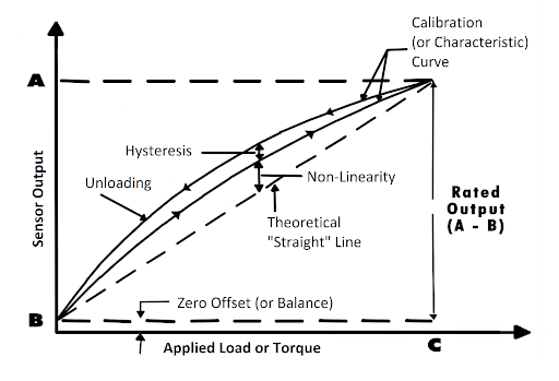
Fig 8. Load Cell Calibration Curve
Load Cell Stiffness
Customers frequently demand to include a load cell in the physical construction of a machine or assembly. They thus want to know how the cell will respond to the forces generated during machine assembly and use.
The designer can seek the physical properties (such as thermal expansion, hardness, and stiffness) of the other elements of the machine (constructed from standard materials) in handbooks and calculate the interactions of his parts based on his design. It will be challenging for the customer to identify a load cell's response to forces since it is built on a flexure, a sophisticated machined item the customer is unaware of.
It's a good idea to think about how a basic flexure responds to loads applied in various directions. Variations of this concept are frequently used in machines and test stands to separate load cells from side loads. In this case, the basic flexure reflects a machine design element rather than an actual load cell.
The simple flexure's thin section functions like a bearing with no friction and a small rotational spring constant. As a result, it could be necessary to determine the material's spring constant and consider it when choosing the machine's reaction characteristics.
The flexure will be distorted sideways by the vector component, FTX or Fex, as illustrated by the dotted outline, if we apply a tensile force, Fn, or a compressive force, Fe, at an angle off of its midline. Although the outcomes appear similar in both circumstances, they are different.
Load Cell Natural Frequency: Lightly Loaded Case
A load cell is often used with a small, light load, like a weigh pan or a small test fixture, attached to the "live" end of the cell. The user is curious about how quickly the cell will react to a change in loading. We can discover some information about a load cell's dynamic response by connecting the output to an oscilloscope and performing a quick test. The cell will produce a damped sine wave train (a sequence of sine waves that gradually approach zero) if we firmly install it on a large block and then softly tap the active end of the cell with a small hammer (a series of sine waves which progressively decrease to zero).
Load Cell Resolution
Electric resistance metal foil strain gages are attached to an elastic flexure element to produce load cells. The load cell is a passive analog device whose continuous-resolution is eventually constrained by noise due to electron motion at about 10-9 volts (1 nanovolt). In practice, the resolution is therefore constrained by the type and quality of the electronic equipment employed and not by the load cell itself. Many devices with affordable prices can resolve a minimum signal level of 0.8 to 1.0 microvolts/count.
Application Of Calibration Loads: Conditioning The Cell
Any transducer that operates based on the deflection of a metal, such as a load cell, pressure transducer, or torque transducer, preserves a record of its prior loads. This effect arises because, despite their tiny size, the minute movements of the metal's crystalline structure have a frictional component that manifests as hysteresis (non-repetition of measurements collected from various directions). The application of three loadings, ranging from zero to a load that surpasses the peak load in the calibration run, can be used to sweep the history out of the load cell before the calibration run. Typically, at least one load between 1300/0 and 140% of the Rated Capacity is applied to properly place and jam the test fixtures into the load cell.
A curve with the properties A-B-C-D-E-F-G-H-I-J-A, as seen in Figure 24, will be achieved if the load cell is set up and the loadings are done appropriately. All the points will fall on a smooth curve, and when the points return back to zero, the curve will close. In addition, if the test is repeated with the correct loadings, the corresponding points between the first and second runs will come quite near to one, proving the repeatability of the data.
Application Of Calibration Loads: Impacts And Hysteresis
The test setup or loading process should always be the first thing to examine if a calibration run produces results that don't follow a smooth curve, don't repeat well, or don't return to zero.
Figure 24 illustrates the outcome of applying loads when the operator was careless and applied a 60% load, for instance. The load cell would work on a tiny hysteresis loop if the weight were lowered gently into the loading rack, applying an impact of 80% load, and then restored to the 600/0 position. This would cause the load cell to read point "P" rather than point "D." The 80% point would result in "R," and the 1000/0 point would result in "S" if the test were to continue. The descending points would be higher than the correct positions, and the return to zero would be incomplete. The same error can occur on a hydraulic test frame if the operator overshoots the proper setting and then allows the pressure to leak back to the correct level. For impacting or overshooting, the sole option is to recondition the cell and restart the test.
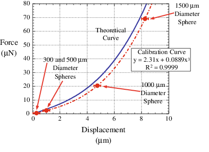
Fig 9. Calibration curve for the load cell
Test Protocols And Calibrations
Usually, load cells are set up in either tension or compression and then calibrated in that mode. If it's necessary to calibrate in the opposite mode as well, the cell must be conditioned in that mode first. Consequently, the calibration data only represents the cell's performance when conditioned in the relevant mode. Therefore, before a logical discussion of the potential sources of error, it is crucial to establish the test protocol (the order of load applications) that the customer intends to utilize.
It is sometimes necessary to develop a factory acceptance to verify that the user's specifications will be satisfied. Users may often adjust their test data for the load cell's nonlinearity for applications with rigorous requirements, eliminating a significant portion of the overall error. Nonlinearity will be a component of their error budget if they cannot do so.
The resolution and stability of the user's signal conditioning electronics determine non-repeatability. The non-repeatability of load cells is often better than that of the load frames, fixtures, and electronics used to calculate it. Hysteresis, the last cause of the error, strongly relies on the loading sequence in the user's test protocol. The amount of hysteresis introduced into the measurements may often be reduced by optimizing the test protocol.
However, there are times when users are forced to operate a load cell in an undefined manner due to an external customer request or an internal product specification, resulting in unexpected hysteresis effects. The user will then be required to accept the worst-case hysteresis as the operational specification.
Furthermore, some cells must function in both modes (tension and compression) during their regular usage cycle without the ability to recondition the cell before switching modes. This causes a state known as toggling. Depending on the flexure material and capacity of the load cell, the magnitude of toggling can vary widely during typical factory production, with the worst case being about equal to or slightly bigger than hysteresis. Fortunately, the toggling issue has several solutions:
- Utilize a load cell with a bigger capacity to run across a smaller range of its capacity. The toggle is reduced when the excursion into the opposing mode is a lesser fraction of the rated capacity.
- Make use of a cell built of a lower toggle material.
- Determine a selection criterion for typical factory production. Most cells have a toggle range that can produce enough units from the typical distribution. The price for this selection is often relatively affordable, depending on the manufacturing construction pace.
- Specify more exact specifications and have the manufacturer provide an estimate for a particular run.
Which characteristic is more important
The importance of load cell characteristics depends on the specific application and requirements. Different characteristics may be more critical in certain situations. Here's a brief overview of the importance of each characteristic:
- Load Cell Accuracy: Accuracy is crucial when precise measurements are required. It indicates how close the load cell's measured values are to the true or reference values. Higher accuracy is desirable for applications where precise weight or force measurements are necessary, such as in laboratory testing or quality control processes.
- Load Cell Linearity: Linearity represents the load cell's ability to provide a linear relationship between the applied force or weight and its output signal. A high level of linearity ensures that the load cell's response is consistent across its operating range. Linearity is particularly important when the load varies over a wide range or when the load cell is used in applications where a linear relationship is essential.
- Load Cell Sensitivity: Sensitivity quantifies how much the load cell's output signal changes per unit change in the applied force or weight. Higher sensitivity allows for more precise measurements of small variations in loads. Applications that involve measuring small forces or weight differentials may require load cells with high sensitivity.
While all these characteristics are important, their relative significance depends on the specific application and the required level of accuracy, linearity, and sensitivity. It's crucial to consider the specific needs and constraints of your application to determine which character is most important for your use case. Additionally, factors such as environmental conditions, cost, durability, and ease of installation and maintenance should also be taken into account when selecting a load cell.
Conclusion
In conclusion, load cells are vital components for accurate weight and force measurements in a wide range of applications. Understanding their characteristics, such as accuracy, linearity, and sensitivity, is crucial for obtaining reliable and precise data.
Load cell accuracy ensures that the measured values closely match the reference values, making it essential for applications where precision is paramount. Linearity guarantees a consistent and predictable relationship between the applied load and the load cell's output, which is particularly important for maintaining accuracy across the load range.
Sensitivity measures the responsiveness of the load cell to changes in applied force or weight, enabling precise detection of small variations. It is particularly valuable in applications where fine-grained measurements are required.
By considering these characteristics in conjunction with the specific requirements of your application, you can select the most suitable load cell for your needs. Whether it's optimizing manufacturing processes, enhancing product quality, or monitoring structural integrity, load cells empower you with the data necessary to make informed decisions and achieve desired outcomes.
So, embrace the power of load cells, unlock their potential, and elevate your measurement capabilities to new heights of accuracy and reliability.
References
https://mhforce.com/top-5-specifications-for-load-cell-accuracy/
https://www.montalvo.com/products/wagezellen-empfindlichkeit-und-auflosung/
Recent Posts
-

From Lab to Launchpad: Pressure Sensor Industry Certifications
In the intricate world of technology and precision engineering, where every measurement matters a …16th Mar 2024 -

Stand Out, Stand Certified: The Art of Pressure Sensor Safety
Stand Out, Stand Certified: The Art of Pressure Sensor Safety Welcome to the world of performance …9th Mar 2024 -

Robotics in Food and beverage Industry
Our lives depend on the food and beverage industry and it is in a constant state of evolution, …5th Mar 2024