
Pressure Measurement Demystified: Manometer and Diaphragm Sensor Explored
In a world where precision reigns supreme, the ability to measure pressure accurately becomes more than just a necessity—it's a crucial art form that empowers industries and technologies spanning from the depths of medical diagnostics to the heights of aerospace exploration. Enter the realm of pressure measurement techniques, where this research embarks on a journey to unravel the inner workings of two distinct yet equally captivating approaches: the venerable manometers and the modern marvels of diaphragm sensors. From the elegant equilibrium of fluid columns in U-tube manometers to the intricate dance of silicon diaphragms translating pressure into electric symphonies, this exploration unveils the heartbeats behind pressure measurement. Discover how these techniques sculpt the landscapes of industries, from shaping medical devices that sustain life to steering the trajectories of rockets that breach the sky. As we delve into the depths of their construction, navigate the terrain of their applications, and weigh the scales of their advantages and limitations, one truth emerges—the art of pressure measurement is a symphony where accuracy orchestrates progress.
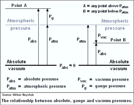
Fig 1. Pressure types
What are the two ways of pressure measurement?
Pressure measurement can be broadly classified into two main categories: direct pressure measurement and indirect pressure measurement. These methods differ in how they obtain pressure information from the system being measured.
- Direct Pressure Measurement: Direct pressure measurement involves directly measuring the pressure at a specific point in a system using mechanical or electronic methods. This category includes techniques where pressure acts directly on a sensing element, and the resulting physical change is measured.
- Indirect Pressure Measurement: Indirect pressure measurement involves inferring the pressure by measuring related parameters and using mathematical relationships. This category includes techniques where pressure is determined indirectly based on its effect on other properties. Some common indirect pressure measurement techniques include
- Pressure Transducers: Convert pressure-related changes into electrical signals (e.g., using capacitance or piezoresistivity).
- Pressure Transmitters: Convert pressure into an analog or digital signal for remote monitoring.
- Pressure Regulators: Control pressure by adjusting flow rates to maintain a desired pressure level.
- Pitot Tubes: Measure fluid velocity, which can be related to pressure changes using Bernoulli's principle.
- Venturi Tubes: Measure fluid flow rates based on pressure differences in a constriction.
- Orifice Plates: Measure fluid flow rates based on pressure differences across an orifice.
Both direct and indirect pressure measurement methods have their advantages and limitations, and the choice between them depends on factors such as accuracy requirements, pressure range, sensitivity, and the nature of the application.
Direct Pressure Measurement Techniques
Direct pressure measurement techniques are methods used to directly measure the pressure of a fluid or gas at a specific point in a system. These techniques provide accurate and real-time pressure readings and are commonly used in various industries and applications, including industrial processes, medical devices, aviation, automotive, and more. Here are some common direct pressure measurement techniques:
- Bourdon Tube Pressure Gauges: Bourdon tubes are curved, hollow tubes that tend to straighten when subjected to pressure. This straightening action is used to move a pointer across a calibrated scale, providing a visual indication of the pressure. Bourdon tube gauges are widely used due to their simplicity, durability, and cost-effectiveness.
- Diaphragm Pressure Sensors: Diaphragm pressure sensors use a flexible diaphragm that deforms under pressure. This deformation is converted into an electrical signal using various techniques such as strain gauges, piezoelectric crystals, or capacitive sensing. These sensors are often used in applications requiring sensitivity to low pressures or compatibility with corrosive substances.
- Piezoelectric Pressure Sensors: Piezoelectric sensors generate an electrical charge in response to applied pressure. These sensors utilize piezoelectric crystals that generate a voltage proportional to the applied pressure. They are commonly used for dynamic pressure measurements and can provide rapid response times.
- Strain Gauge Pressure Transducers: Strain gauges are bonded to a pressure-sensitive diaphragm. When the diaphragm is subjected to pressure, it deforms, causing the strain gauges to change their resistance. This change in resistance is then converted into an electrical signal, which can be calibrated to provide pressure readings.
- Capacitive Pressure Sensors: Capacitive pressure sensors consist of two plates separated by a small gap. The capacitance between the plates changes with the applied pressure, leading to a change in the electrical signal. These sensors are known for their high accuracy and stability.
- Resonant Wire Pressure Transducers: Resonant wire transducers use a wire under tension that vibrates at its natural resonant frequency. When pressure is applied, the tension in the wire changes, altering its resonant frequency. This change is used to calculate the pressure.
- Piston Manometers: Piston manometers use a piston to balance the applied pressure. The pressure is balanced when the piston reaches a position where its weight is counteracted by the pressure force. The height of the piston is then used to calculate the pressure.
- Deadweight Testers: Deadweight testers involve using known masses on a piston to generate precise pressure. The pressure is determined by the gravitational force acting on the masses and the effective piston area.
- Quartz Crystal Pressure Sensors: Quartz crystals resonate at a frequency that is sensitive to pressure changes. By measuring the frequency change, the pressure can be determined.
- Optical Pressure Sensors: These sensors utilize the deflection of a beam of light due to pressure-induced mechanical changes in an optical element. The deflection is converted into an electrical signal for pressure measurement.
Each technique has its advantages and limitations, and the choice of technique depends on factors such as the required accuracy, sensitivity, range, environmental conditions, and intended application.
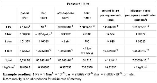
Fig 2. Pressure units
What is a manometer?
A manometer is a device used for measuring the pressure of liquids, gases, or vapors in a closed system. It consists of a column of liquid, usually mercury or a water-based fluid, contained within a transparent tube. The height of the liquid column in the tube is proportional to the pressure being measured. Manometers are commonly used in various industrial, scientific, and engineering applications to provide a simple and direct way of measuring pressure differences or absolute pressures.
There are different types of manometers, each designed for specific pressure measurement needs:
- Simple Manometer: This basic type consists of a U-shaped tube partially filled with a liquid. One leg of the U-tube is connected to the pressure source, and the other leg is left open to the atmosphere. The pressure difference between the two legs is indicated by the difference in liquid levels in the tube. Simple manometers are suitable for measuring gauge pressure (pressure relative to atmospheric pressure).
- Differential Manometer: Differential manometers are used to measure the difference in pressure between two points in a system. They have two legs connected to separate pressure sources, and the difference in liquid levels indicates the pressure difference between the two points.
- Inclined Manometer: Inclined manometers use a tilted U-tube filled with liquid. This design allows for greater sensitivity in pressure measurement compared to a vertical U-tube. They are often used when the pressure difference to be measured is small.
- U-Tube Manometer: The standard U-tube manometer is a simple vertical tube filled with liquid. One end is connected to the pressure source, and the other is open to the atmosphere. The difference in liquid levels indicates the pressure difference.
- Well-Type Manometer: Well manometers have a reservoir at the bottom that ensures a constant supply of liquid to the column, preventing fluctuations due to changes in fluid density.
- Mercury Manometer: In some cases, mercury is used as the liquid in manometers due to its high density and low vapor pressure. However, mercury poses health and environmental risks, so alternatives are often preferred.
- Water Manometer: Water is commonly used as the liquid in manometers for low-pressure measurements. It is safe and readily available.
Manometers provide a visual and direct measurement of pressure but may have limitations in terms of the pressure range they can measure and the potential for errors due to variations in fluid density, temperature, and atmospheric pressure. Despite these limitations, manometers remain valuable tools for various pressure measurement applications, especially in situations where accuracy and sensitivity are not critical.
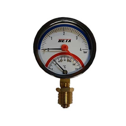
Fig 3. Manometer
How does a manometer work?
A manometer works based on the principle that the height of a liquid column in a tube is directly proportional to the pressure being measured. The basic idea is to balance the pressure of the fluid being measured against the gravitational force acting on the liquid column inside the tube. The height of the liquid column indicates the pressure difference between the two points connected to the manometer.
Here's how a simple U-tube manometer works:
- Setup: Imagine a U-shaped tube that is partially filled with a liquid, such as mercury or water. One end of the U-tube is connected to the point where you want to measure the pressure (P1), and the other end is left open to the atmosphere (P2).
- Pressure Difference: When the pressure at the connected point (P1) is different from atmospheric pressure (P2), the pressure difference causes the liquid in one leg of the U-tube to rise and the liquid in the other leg to fall. This creates an imbalance in the liquid levels.
- Balancing: The imbalance in liquid levels creates a height difference (h) between the two liquid columns. The pressure difference (ΔP) between the connected point and the atmosphere can be calculated using the equation ΔP = ρgh, where:
- ΔP is the pressure difference
- ρ is the density of the liquid in the manometer tube
- g is the acceleration due to gravity
- h is the height difference between the liquid levels
- Pressure Measurement: By measuring the height difference (h) of the liquid column, you can determine the pressure difference between the two points. If atmospheric pressure (P2) is known, you can calculate the absolute pressure at the connected point (P1) using the equation P1 = P2 + ΔP.
It's important to note that the density of the liquid and the acceleration due to gravity are constants, so changes in these values will not affect the proportional relationship between the pressure difference and the height of the liquid column.
Different types of manometers, such as the U-tube, inclined, and well-type manometers, have slightly different designs and principles of operation. Some manometers may incorporate additional features, such as reservoirs to maintain a constant supply of liquid, to enhance accuracy and usability.
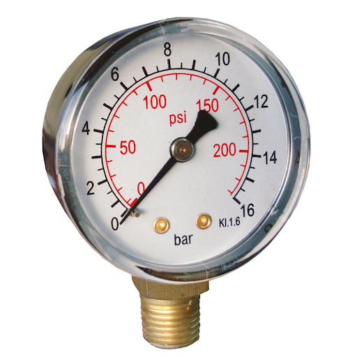
Fig 4. Manometer
What are the manometer types?
There are several types of manometers, each with its design and application. Manometers are classified based on their structure and the specific pressure measurement needs they address. Here are some common types of manometers:
- U-Tube Manometer: This is one of the simplest and most common types of manometer. It consists of a U-shaped tube partially filled with a liquid, such as mercury or water. One leg of the U-tube is connected to the pressure source, and the other leg is open to the atmosphere. The difference in liquid levels in the two legs indicates the pressure difference.
- Inclined Manometer: In an inclined manometer, the U-shaped tube is tilted at an angle instead of being vertical. This design increases the sensitivity of the manometer to small pressure differences. Inclined manometers are often used when the pressure difference to be measured is small.
- Well-Type Manometer: Well manometers have a reservoir at the bottom of the U-tube that maintains a constant supply of liquid. This helps ensure a consistent and accurate pressure reading by preventing fluctuations due to changes in fluid density.
- Mercury Manometer: This type of manometer uses mercury as the liquid inside the tube. Mercury's high density makes it suitable for measuring high pressures. However, due to environmental and health concerns associated with mercury, alternatives are often preferred.
- Water Manometer: Water is commonly used as the liquid in manometers for measuring low-pressure differences. It's safe, readily available, and suitable for most practical applications.
- Differential Manometer: Differential manometers are used to measure the pressure difference between two points. They have two connected legs, each with its pressure connection. The difference in liquid levels in the two legs provides a direct measurement of the pressure difference.
- Micromanometer: This is a highly sensitive manometer used for measuring very small pressure differences. It often includes mechanisms for magnifying the readings, allowing precise measurements in applications like fluid dynamics and aerodynamics.
- Digital Manometer: While traditional manometers use liquid columns for measurement, digital manometers employ electronic sensors to measure pressure. They provide digital readouts and often offer features like data logging and pressure unit conversions.
- McLeod Gauge: This specialized manometer is used to measure very low pressures, approaching vacuum levels. It uses a mercury column and relies on the compressibility of the gas being measured to create a pressure difference in the manometer.
- Pitot Tube: Although not a traditional manometer, the Pitot tube is used to measure fluid velocity in pipes or ducts. It consists of a tube facing the fluid flow and a perpendicular tube connected to a U-tube manometer. The pressure difference between the two tubes is used to calculate fluid velocity.
These are just a few examples of manometer types, and some variations and combinations cater to specific applications and requirements in different fields such as engineering, fluid dynamics, and industrial processes.
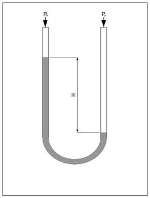
Fig 5. U-tube manometer
Comparing table
here's a comparison table outlining the key characteristics of different types of manometers:
Table 1. Manometer types comparing
| Manometer Type | Principle | Liquid Used | Sensitivity | Pressure Range | Applications |
| U-Tube | Vertical tube | Mercury, water, etc. | Moderate | Low to moderate | General pressure measurement |
| Inclined | Tilted U-tube | Mercury, water, etc. | High | Low to moderate | Sensitive pressure measurement |
| Well-Type | Reservoir maintained | Mercury, water, etc. | High | Low to moderate | Stable pressure readings |
| Differential | Two connected legs | Mercury, water, etc. | Variable | Low to High | Measuring pressure differences |
| Micromanometer | High sensitivity | Mercury, oil, etc. | Very high | Low to moderate | Precision measurements |
| Digital | Electronic sensors | None | Variable | Low to High | Modern, data-driven measurements |
| McLeod Gauge | Vacuum measurement | Mercury, oil, etc. | Very high | Very low | Ultra-low pressure measurements |
| Pitot Tube | Fluid velocity | None | N/A | N/A | Airflow and fluid velocity |
Please note that the characteristics mentioned in the table can vary depending on specific designs and manufacturers. The choice of manometer type depends on factors like the desired pressure range, sensitivity, accuracy, and the application's requirements.
What is the manometer used for?
Manometers are used for measuring the pressure of liquids, gases, or vapors in various applications across different industries. They provide a simple and direct way to gauge pressure differences and are particularly useful in situations where accuracy, real-time measurements, and visual indication of pressure are needed. Here are some common applications of manometers:
- Industrial Processes: Manometers are widely used in industrial settings to monitor and control pressure in processes such as manufacturing, chemical production, and HVAC systems.
- Fluid Dynamics Research: Manometers are used in fluid dynamics experiments to measure pressure variations in pipes, channels, and other fluid-carrying systems.
- Medical Devices: Manometers are utilized in medical devices like blood pressure monitors (sphygmomanometers) to measure blood pressure in patients.
- Aeronautics and Aviation: Manometers are employed in aviation instruments to measure airspeed, altitude, and cabin pressure.
- Hydraulic and Pneumatic Systems: Manometers are used to ensure proper pressure levels in hydraulic systems, pneumatic tools, and machinery.
- Automotive Industry: Manometers are used to measure exhaust gas pressure, fuel system pressure, and tire pressure in vehicles.
- Laboratory Experiments: Manometers play a role in scientific experiments involving pressure measurements, such as studies in fluid mechanics and thermodynamics.
- Gas Delivery Systems: In semiconductor manufacturing and gas delivery systems, manometers help control the pressure of gases used in the process.
- Boilers and Steam Systems: Manometers monitor pressure levels in boilers and steam systems to ensure safe and efficient operation.
- Research and Development: Manometers are used in various research and development applications where pressure measurement is critical, such as material testing and environmental studies.
- Environmental Monitoring: Manometers can be used in environmental monitoring systems to measure atmospheric pressure and pressure changes due to weather conditions.
- Quality Control: Manometers are employed in quality control processes to ensure consistent pressure levels in production lines.
- Fluid Flow Measurement: In conjunction with Pitot tubes, manometers can be used to measure fluid flow velocities in pipes, channels, and ducts.
- Gas Leakage Detection: Manometers can be used to detect gas leaks by measuring pressure differences between gas sources and surrounding areas.
- Calibration and Testing: Manometers serve as calibration references for other pressure-measuring devices.
These are just a few examples of the many applications of manometers. Their ability to provide direct and real-time pressure measurements makes them essential tools across industries where pressure monitoring is crucial for safety, efficiency, and quality control.
Does a manometer have limitations?
Yes, manometers do have limitations and considerations that should be taken into account when using them for pressure measurement. Here are some of the key limitations:
- Limited Pressure Range: Different types of manometers have varying pressure ranges they can effectively measure. Some manometers are suitable for low-pressure measurements, while others are better for high pressures. Using a manometer beyond its specified range can lead to inaccurate readings or even damage.
- Fluid Density Variations: Manometers rely on the density of the liquid in the column. Variations in the density of the liquid due to temperature changes can affect the accuracy of measurements.
- Incompatibility with Certain Fluids: Some manometer liquids are not compatible with certain chemicals or substances, which can lead to contamination or damage.
- Gravity Variations: Changes in local gravitational acceleration (due to elevation or location) can affect the accuracy of measurements. However, this impact is typically minor.
- Accuracy and Precision: While manometers can provide direct and real-time measurements, their accuracy and precision might not be as high as some other electronic pressure measuring devices.
- Vibration and Mechanical Shock: Manometers are mechanical devices and can be sensitive to vibrations or mechanical shocks, potentially affecting their readings.
- Environmental Conditions: Extreme temperatures or atmospheric pressure changes can influence manometer measurements.
- Fluid Evaporation and Leaks: Some manometer liquids, like mercury, are volatile or can leak, presenting safety and environmental hazards.
- Health and Safety Concerns: Mercury, historically used in manometers, poses health risks if not handled properly. Alternatives are often preferred for safety reasons.
- Maintenance and Calibration: Manometers require periodic calibration and maintenance to ensure accurate readings.
- Measurement Readability: Reading the liquid level accurately can be challenging, especially in situations where the meniscus is not easily distinguishable.
- Pressure Pulsations: Rapid pressure fluctuations can cause oscillations in the liquid column, making it difficult to obtain stable measurements.
- Limited Digital Display: Traditional manometers don't provide digital readouts, which can be less convenient for precise readings.
- Size and Portability: Some manometers can be bulky and less portable compared to modern electronic pressure sensors.
Despite these limitations, manometers remain valuable tools for various pressure measurement applications. The choice of manometer type and a proper understanding of its limitations is important to ensure accurate and reliable measurements.
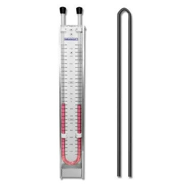
Fig 6. U-tube manometer
Advantages and disadvantages of using the manometer
Using a manometer for pressure measurement has its advantages and disadvantages, depending on the specific application and requirements. Here are some of the key advantages and disadvantages of using a manometer:
Advantages:
- Direct Measurement: Manometers provide a direct visual indication of pressure, which can be advantageous when real-time readings are required.
- Simplicity: Manometers are relatively simple devices with few moving parts, making them easy to understand, install, and operate.
- No Power Requirement: Most traditional manometers do not require a power source, as they rely on gravity and fluid pressure to function.
- Low Cost: Manometers are often more cost-effective than some electronic pressure sensors, making them suitable for applications where budget constraints exist.
- Stable Measurements: Well-designed manometers, especially those with a reservoir or constant liquid supply, can provide stable and reliable pressure measurements over time.
- Immediate Response: Manometers react quickly to pressure changes, making them suitable for dynamic pressure measurements.
- Wide Range of Types: There are various types of manometers, each designed to suit specific pressure ranges and applications.
Disadvantages:
- Limited Accuracy: Compared to modern electronic pressure sensors, manometers may have lower accuracy and precision, particularly for highly sensitive measurements.
- Subject to Human Error: Reading the liquid level accurately requires careful observation, and human error can introduce inaccuracies.
- Pressure Range Limitations: Different types of manometers have specific pressure range limitations. Choosing the wrong type for the intended pressure range can lead to inaccurate readings or damage.
- Fluid Density Variations: Changes in fluid density due to temperature fluctuations can affect measurement accuracy.
- Environmental Sensitivity: Environmental factors such as temperature, altitude, and atmospheric pressure changes can impact measurements.
- Maintenance: Manometers require periodic calibration, maintenance, and cleaning to ensure accurate and reliable readings.
- Limited Portability: Traditional manometers can be bulkier and less portable than modern electronic pressure sensors.
- Limited Digital Output: Most traditional manometers provide analog readings and do not offer digital output, which might be less convenient for data collection and analysis.
- Incompatibility with Some Fluids: Some manometer liquids may not be compatible with certain substances, limiting their applicability in certain industries.
- Health and Safety Concerns: Traditional mercury manometers pose health and environmental risks due to mercury toxicity. Alternatives are recommended for safety reasons.
In summary, manometers are valuable tools for pressure measurement in various applications, especially where real-time monitoring and simplicity are important. However, they do have limitations, particularly in terms of accuracy, environmental sensitivity, and compatibility with certain fluids. Careful consideration of the advantages and disadvantages is essential when choosing a manometer for a specific pressure measurement task.
What is a bourdon tube?
A Bourdon tube is a curved, hollow metal tube that is used as a sensing element in pressure measurement devices, particularly in Bourdon tube pressure gauges. It was invented by French engineer Eugène Bourdon in the 19th century. The Bourdon tube's unique design allows it to convert pressure changes into mechanical motion, which is then translated into a visual pressure reading on a gauge or other measurement instrument.
The Bourdon tube operates on the principle that when pressure is applied to the inside of the curved tube, it tends to straighten or uncoil. This deformation of the tube is proportional to the pressure applied. The tube is typically closed at one end and connected to the pressure source at the other.
The key components of a Bourdon tube include
- a Curved Tube: The curved shape of the tube is essential for its operation. It can be coiled into a C-shape, helical shape, or spiral shape.
- Linkage: As the tube straightens or uncoils due to pressure, a linkage mechanism connected to the free end of the tube translates this motion into a rotational movement.
- Pointer: The rotational movement of the linkage is then used to move a pointer across a calibrated scale on the gauge, providing a visual indication of the pressure.
Bourdon tubes are often made of metals like brass, stainless steel, or other alloys, depending on the application and the media being measured (gas, liquid, or vapor). The tube's geometry, material properties, and curvature are carefully designed to provide a linear relationship between pressure and tube deformation.
Bourdon tubes are widely used due to their simplicity, durability, and cost-effectiveness. They are suitable for measuring a range of pressures, from low to high, depending on the tube's design and materials. However, it's important to note that Bourdon tubes can have limitations in terms of accuracy, especially for very sensitive or precise pressure measurements.
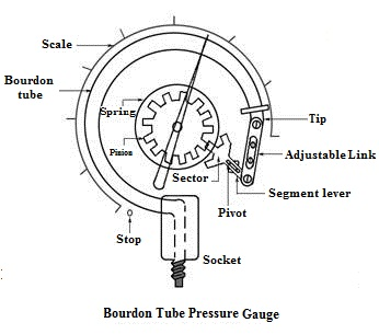
Fig 7. Bourdon tube pressure gauge
Bourdon tube structure
A Bourdon tube is a key component in Bourdon tube pressure gauges and various other pressure measurement devices. It consists of a curved, hollow metal tube that deforms when pressure is applied to its interior. The deformation of the tube is then converted into mechanical motion, which is used to indicate the pressure on a gauge's scale. Here is a breakdown of the structure and components of a typical Bourdon tube:
- Curved Tube: The main body of the Bourdon tube is a curved, hollow metal tube. The shape of the tube can vary, but common configurations include C-shaped, helical (coil), or spiral forms. The curvature and material properties of the tube are carefully chosen to ensure accurate pressure measurement.
- Free End: One end of the Bourdon tube is open or free. This end is sealed at the rim, and it is the portion of the tube that undergoes deformation when pressure is applied.
- Linkage Mechanism: The free end of the Bourdon tube is connected to a mechanical linkage mechanism. This linkage transforms the linear deformation of the tube into rotational movement.
- Levers and Gears: The mechanical linkage may include levers and gears that amplify the small linear motion of the Bourdon tube into a larger rotational motion. This amplification helps move the pointer across the gauge's scale.
- Pointer: The rotational motion of the linkage is ultimately transmitted to a pointer. The pointer moves along a calibrated scale on the gauge's face, providing a visual indication of the pressure being measured.
- Calibrated Scale: The gauge's face features a calibrated scale marked with pressure units. The scale allows users to read the pressure directly from the position of the pointer.
- Pressure Inlet: The other end of the Bourdon tube is connected to the pressure source through an inlet. This inlet allows the pressure in the system being measured to act on the inside of the Bourdon tube.
The structure of the Bourdon tube and its associated components work in concert to convert the applied pressure into mechanical motion and visual pressure indication. While the basic principles remain consistent across different Bourdon tube designs, variations in curvature, material, linkage design, and scale configuration can result in different pressure ranges, sensitivities, and accuracies for different types of Bourdon tube pressure gauges.
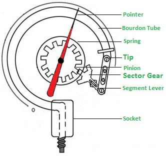
Fig 8. Bourdon tube structure
Bourdon tube working principle
The Bourdon tube operates based on the principle of elastic deformation. When pressure is applied to the inside of a curved tube, it changes shape, transitioning from its curved state to a more straightened configuration. This deformation is directly proportional to the pressure applied, allowing the Bourdon tube to function as a pressure-sensing element. Here's how the Bourdon tube working principle functions:
- Curved Tube Configuration: The Bourdon tube is typically constructed as a curved, hollow tube with an elliptical or C-shaped cross-section. The tube might be coiled in a C-shape, helix, or spiral form. The free end of the tube is sealed, and the other end is connected to the pressure source (such as a pipe or container) through an inlet.
- Pressure Application: When the pressure in the system increases, the pressure inside the Bourdon tube also rises. As a result, the tube attempts to return to a straighter configuration due to the internal pressure pushing against the curved walls of the tube.
- Deformation: The increase in internal pressure causes the curved tube to begin straightening or uncoiling. This deformation can be observed in the movement of the free end of the tube.
- Linkage and Movement: The free end of the Bourdon tube is linked to a mechanical linkage mechanism. As the tube uncoils, it causes the linkage to move. This movement is then transmitted to a pointer attached to the linkage.
- Pointer and Scale: The pointer moves across a calibrated scale on the pressure gauge, providing a visual indication of the pressure being measured. The scale is marked in pressure units, allowing users to directly read the pressure value.
- Linear Relationship: The design of the Bourdon tube is carefully engineered to ensure a linear relationship between pressure and tube deformation. This means that the degree of tube straightening is directly proportional to the pressure applied within the tube.
The key factors that influence the accuracy and sensitivity of Bourdon tube pressure gauges include the tube's material properties, geometry (cross-sectional shape, curvature, and length), and the design of the mechanical linkage. While Bourdon tube pressure gauges are simple and reliable instruments, it's important to note that they may not be suitable for extremely high precision or sensitivity applications due to limitations in their construction and mechanical behavior.
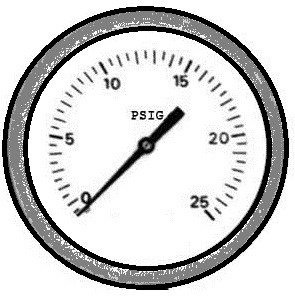
Fig 9. Bourdon tube
What are the bourdon tube types?
Bourdon tubes come in various types, each designed to suit specific pressure measurement needs and applications. The curvature, cross-sectional shape, and geometry of the Bourdon tube influence its sensitivity and pressure range. Here are some common types of Bourdon tubes:
- C-Type Bourdon Tube: This is one of the simplest and most common types. The tube is shaped like the letter "C" and is often used for measuring moderate pressure ranges. It offers good sensitivity and is suitable for a wide range of applications.
- Helical Bourdon Tube: This type features a helix or coil shape. The helical design allows for increased sensitivity to pressure changes, making it useful for applications requiring higher precision. It is often used in pressure gauges for scientific and laboratory purposes.
- Spiral Bourdon Tube: The spiral Bourdon tube has a spiral or scroll-like shape. It offers excellent sensitivity and is often used in pressure gauges requiring accurate readings at low pressures, such as vacuum pressure measurement.
- Coaxial Bourdon Tube: This type features multiple concentric tubes that can amplify the movement of the inner tube, enhancing sensitivity. Coaxial Bourdon tubes are used for high-pressure applications where accurate measurements are essential.
- Helical and Spiral Compound Tube: This design combines helical and spiral shapes, offering a balance between sensitivity and pressure range. It's often used in industrial pressure gauges.
- Elliptical Bourdon Tube: The elliptical cross-section of this tube allows for greater sensitivity to pressure changes. It's commonly used for precision pressure measurement in laboratory and research settings.
- Diaphragm Type Bourdon Tube: This variation incorporates a diaphragm on the free end of the Bourdon tube. The diaphragm amplifies the movement of the tube, enhancing sensitivity and accuracy.
- Overpressure Protected Bourdon Tube: These tubes have protective features to prevent damage from overpressure situations. They are used in applications where sudden pressure spikes can occur.
- Flattened Tube Bourdon Tube: In this type, the Bourdon tube has a flattened or oval cross-section. This design offers increased sensitivity to small pressure changes and is used in precision gauges.
- Spiral and Helical Compound Tube: This design combines the advantages of both spiral and helical Bourdon tubes, providing a balance between sensitivity and pressure range.
The choice of Bourdon tube type depends on factors such as the pressure range, desired sensitivity, accuracy requirements, and the specific application. Different types of Bourdon tubes are selected to ensure optimal performance for various pressure measurement scenarios.
Comparing table of Bourdon tube types
Here's a simplified comparing table of different types of Bourdon tubes commonly used for pressure measurement:
Table 2. Bourdon tube types comparison
| Bourdon Tube Type | Description | Advantages | Limitations | Applications |
| C-Type Bourdon Tube | Coiled flat tube with elliptical cross-section | Good sensitivity, suitable for low-pressure measurements | Limited pressure range, susceptibility to overpressure | HVAC, pneumatic systems |
| Spiral Bourdon Tube | Coiled tube with spiral configuration | High sensitivity, linear response | Limited pressure range, complex manufacturing | HVAC, laboratory equipment |
| Helical Bourdon Tube | Coiled tube in helical shape | Wide pressure range, robust construction | Lower sensitivity compared to other types | Industrial processes, machinery |
| Spiral Helical Bourdon Tube | Combination of spiral and helical configurations | High pressure range, good accuracy | More complex design, higher manufacturing cost | Hydraulic systems, industrial applications |
| Elliptical Bourdon Tube | Tube with elliptical cross-section | Excellent sensitivity and accuracy | Limited pressure range, susceptible to external forces | Laboratory, precision instruments |
Please note that this table provides a general overview and might not include all specific advantages, limitations, and applications for each Bourdon tube type. The choice of Bourdon tube type depends on factors such as pressure range, accuracy requirements, environmental conditions, and application specifics.
What are bourdon tube applications?
Bourdon tubes find applications in a wide range of industries and scenarios where pressure measurement is crucial. They are particularly well-suited for applications that require real-time pressure readings, simplicity, and reliability. Here are some common applications of Bourdon tube pressure gauges and devices:
- Industrial Processes: Bourdon tube pressure gauges are extensively used in industrial settings to monitor and control pressure in processes such as manufacturing, chemical production, oil and gas, and power generation.
- HVAC Systems: Heating, ventilation, and air conditioning systems use Bourdon tube pressure gauges to monitor pressures in refrigeration circuits, air ducts, and fluid systems.
- Steam Boilers: Bourdon tube pressure gauges are employed in steam boilers to monitor steam pressure and ensure safe operation.
- Hydraulic Systems: Bourdon tube gauges are used in hydraulic systems to monitor fluid pressure in machinery, vehicles, and equipment.
- Pneumatic Systems: They are used in pneumatic systems to measure air pressure in tools, machines, and industrial processes.
- Laboratory Equipment: Bourdon tube pressure gauges are used in laboratory setups for pressure measurements in experiments and research.
- Medical Devices: They are used in medical instruments like anesthesia machines, ventilators, and autoclaves to monitor gas and fluid pressures.
- Aerospace and Aviation: Bourdon tube pressure gauges are used in aircraft to monitor cabin pressure, hydraulic systems, and fuel pressure.
- Automotive Industry: They are used in vehicles to measure tire pressure, fuel pressure, and oil pressure.
- Water Supply Systems: Bourdon tube gauges are employed in water treatment plants and distribution systems to monitor water pressure.
- Fire Protection Systems: They are used in fire sprinkler systems to monitor water pressure in fire suppression networks.
- Gas Delivery Systems: Bourdon tube pressure gauges are used in semiconductor manufacturing and gas delivery systems to control and monitor gas pressures.
- Pressure Regulators: They are used in conjunction with pressure regulators to control and maintain pressure levels.
- Quality Control: Bourdon tube gauges are used in manufacturing and production lines to ensure consistent pressure levels and product quality.
- Environmental Monitoring: They are used to monitor atmospheric pressure changes and weather conditions.
- Research and Development: Bourdon tube pressure gauges are used in various research and development applications where pressure measurement is critical, such as materials testing and fluid dynamics studies.
These applications showcase the versatility of Bourdon tube pressure gauges across diverse industries, where they contribute to safety, process control, efficiency, and quality assurance.

Fig 10. Bourdon tube
Bourdon tube limitation
While Bourdon tubes are widely used and have many advantages, they also come with certain limitations that should be considered when selecting them for pressure measurement applications. Here are some of the limitations of Bourdon tubes:
- Limited Accuracy: Bourdon tubes might not provide the same level of accuracy as some modern electronic pressure sensors, especially for highly sensitive measurements.
- Non-Linearity: While Bourdon tubes are designed to be linear over a certain pressure range, they can exhibit non-linear behavior at the extreme ends of their range.
- Hysteresis: Bourdon tubes can exhibit hysteresis, which means that their readings might vary depending on whether the pressure is increasing or decreasing. This can affect measurement precision.
- Temperature Sensitivity: Changes in ambient temperature can affect the material properties of the Bourdon tube and consequently influence pressure readings.
- Pressure Range Limitations: Different types of Bourdon tubes are designed for specific pressure ranges. Using a Bourdon tube outside of its specified range can lead to inaccurate readings or damage.
- Mechanical Wear and Fatigue: Over time, the repeated deformation of the Bourdon tube due to pressure fluctuations can lead to mechanical wear and fatigue, affecting long-term accuracy.
- Environmental Factors: External factors such as vibrations, shocks, and extreme conditions can impact the performance of Bourdon tubes.
- Vibration Sensitivity: Bourdon tubes can be sensitive to vibrations, which might lead to fluctuations in pressure readings.
- Limited Digital Output: Traditional Bourdon tube gauges provide analog readings. While modern electronic versions with digital outputs exist, traditional designs might not be compatible with digital data collection systems without additional equipment.
- Fluid Compatibility: The choice of Bourdon tube material should match the compatibility with the medium being measured to avoid corrosion or contamination.
- Overpressure Limitation: Bourdon tubes can be damaged if subjected to pressures significantly higher than their designed range.
- Response Time: The mechanical nature of Bourdon tubes means that their response time might be slower compared to electronic pressure sensors.
- Bulk and Size: Traditional Bourdon tube gauges can be bulkier and less portable compared to modern electronic pressure sensors.
- Health and Safety Concerns: Mercury-filled Bourdon tubes, which were used historically, pose health and environmental risks due to mercury's toxicity. Alternatives are recommended for safety reasons.
- Calibration and Maintenance: Bourdon tubes require periodic calibration and maintenance to ensure accurate readings.
Despite these limitations, Bourdon tubes remain valuable tools for pressure measurement in various applications. When selecting a pressure measurement solution, it's important to assess the specific requirements of your application and consider the advantages and limitations of Bourdon tubes about other available options.
Bourdon tube pros and cons
Certainly, here's a concise list of the pros and cons of Bourdon tube pressure gauges:
Pros:
- Direct Visual Indication: Bourdon tube gauges provide a direct visual indication of pressure readings, allowing for real-time monitoring.
- Simplicity: These gauges are relatively simple in design, making them easy to install, understand, and operate.
- No Power Requirement: Most Bourdon tube gauges do not require an external power source for operation.
- Cost-Effectiveness: Bourdon tube gauges are generally more affordable than some modern electronic pressure sensors.
- Stable Measurements: Well-designed Bourdon tubes with proper maintenance can provide stable and reliable pressure readings over time.
- Immediate Response: Bourdon tube gauges respond quickly to pressure changes, making them suitable for dynamic pressure measurements.
- Variety of Ranges: Bourdon tubes come in various types suitable for different pressure ranges and sensitivities.
Cons:
- Limited Accuracy: Bourdon tubes might not offer the same level of accuracy as more advanced electronic pressure sensors.
- Non-Linearity: They can exhibit non-linear behavior, particularly at the extreme ends of their pressure range.
- Temperature Sensitivity: Changes in ambient temperature can affect Bourdon tube measurements.
- Hysteresis: Bourdon tubes can show hysteresis, causing different readings for pressure increases and decreases.
- Vibration and Shock Sensitivity: They can be sensitive to vibrations and mechanical shocks, leading to fluctuations in readings.
- Limited Digital Output: Traditional Bourdon tube gauges provide analog readings, which might require additional equipment for digital data collection.
- Environmental Impact: External factors like extreme conditions, vibrations, and shocks can influence their performance.
- Fluid Compatibility: The material of the Bourdon tube must be compatible with the medium being measured to avoid corrosion or contamination.
- Overpressure Limitation: They can be damaged if subjected to pressures significantly higher than their designed range.
- Health and Safety Concerns: Mercury-filled Bourdon tubes pose health and environmental risks. Alternatives are preferred for safety.
- Maintenance: Periodic calibration and maintenance are needed to ensure accurate readings.
- Response Time: Mechanical nature might result in slower response times compared to electronic sensors.
- Size and Bulk: Traditional designs can be bulkier and less portable compared to modern electronic pressure sensors.
- Limited Use in Precise Applications: Some high-precision applications might require more accurate and sensitive pressure sensors.
- Pressure Range Restrictions: Different Bourdon tube types have specific pressure range limitations.
When considering using Bourdon tube gauges, it's essential to weigh these pros and cons against the specific requirements of your application and consider alternative pressure measurement solutions if needed.
What is a diaphragm sensor?
A diaphragm sensor, also known as a diaphragm pressure sensor or pressure transducer, is a type of pressure measurement device that utilizes a flexible diaphragm to convert applied pressure into an electrical signal. This signal can then be interpreted and used for various applications, including pressure monitoring, control systems, and data acquisition. Diaphragm sensors are commonly used in industries where accurate and reliable pressure measurements are essential.
Diaphragm sensors have the advantage of being able to provide accurate and reliable measurements over a wide range of pressure values. They can be designed to withstand different pressure ranges, making them suitable for various applications from low pressures to high pressures. Additionally, diaphragm sensors can be engineered to provide various levels of sensitivity and precision.
Diaphragm sensors find applications in industries such as automotive, aerospace, medical, industrial automation, HVAC, and more. They are often used in situations where continuous monitoring, control, and integration with electronic systems are required.
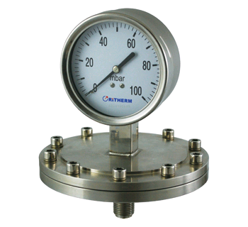
Fig 11. Elastic diaphragm gauges
How is a diaphragm sensor constructed?
A diaphragm sensor, also known as a diaphragm pressure sensor or pressure transducer, consists of several key components designed to accurately measure pressure and convert it into an electrical signal. The construction of a diaphragm sensor involves intricate engineering to ensure accuracy, reliability, and compatibility with various applications. Here's a general overview of the construction of a diaphragm sensor:
- Diaphragm Material: The core component of the diaphragm sensor is the flexible diaphragm itself. Diaphragms are made from materials like stainless steel, silicon, elastomers, or ceramics. The choice of material depends on factors such as the pressure range, the medium being measured (liquid or gas), and the environment (corrosive, high-temperature, etc.).
- Diaphragm Design: The diaphragm is designed to deform when subjected to pressure. Its shape and thickness are carefully engineered to ensure a linear relationship between pressure and deformation.
- Pressure Port: The diaphragm is exposed to the pressure being measured through a pressure port or inlet. This is the point where the pressure is applied to the diaphragm.
- Cavity and Sealing: The diaphragm is sealed within a cavity, often made of robust material like stainless steel. This cavity contains the necessary components for signal transduction and protection from external elements.
- Strain Gauges or Sensing Elements: Strain gauges are bonded to the surface of the diaphragm. These gauges are responsible for measuring the strain or deflection of the diaphragm as it flexes due to applied pressure. The strain gauges are typically resistive, and changes in resistance due to deformation are used to calculate the pressure.
- Wiring and Connections: The strain gauges are wired into a Wheatstone bridge circuit, which helps amplify and convert the small changes in resistance into a more measurable electrical signal.
- Isolation and Protection: To protect sensitive components, the diaphragm sensor might include additional layers of material or coatings for insulation, temperature compensation, and protection against environmental factors.
- Electronics and Signal Conditioning: The amplified signal from the Wheatstone bridge is sent to electronic circuits for signal conditioning, amplification, linearization, and temperature compensation. These processes ensure that the output signal accurately represents the pressure applied to the diaphragm.
- Output Circuitry: The conditioned electrical signal is then converted into an output format suitable for the application. This can be an analog voltage or current, or a digital signal like a 4-20 mA current loop or digital communication protocol (such as I2C or SPI).
- Housing: The entire assembly is housed in a protective casing made of materials resistant to environmental conditions and compatible with the application's requirements.
- Pressure Port Design: Depending on the application, the pressure port might be designed to accommodate different connection types, like threaded fittings, flanges, or adapters.
The construction of a diaphragm sensor involves intricate engineering to ensure accuracy, sensitivity, and reliability. Different diaphragm sensor designs might have variations in their components and construction, but the fundamental principle remains the same: converting pressure into an electrical signal through the deformation of a flexible diaphragm.
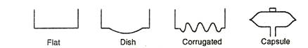
Fig 12. Diaphragm component
How does a diaphragm sensor work?
A diaphragm sensor, also known as a diaphragm pressure sensor or pressure transducer, works by converting applied pressure into a measurable electrical signal. This signal can then be processed, amplified, and used for various applications such as pressure monitoring, control, and data acquisition. Here's how a diaphragm sensor works:
- Diaphragm Deformation: The core of the diaphragm sensor is a flexible diaphragm made of materials like stainless steel, silicon, or elastomers. When pressure is applied to the diaphragm through a pressure port, it deforms due to the force exerted by the pressure. The diaphragm's deflection is directly proportional to the applied pressure.
- Strain Gauge Measurement: Bonded to the surface of the diaphragm are strain gauges, which are resistive elements that change their electrical resistance when subjected to mechanical strain or deformation. As the diaphragm deforms under pressure, the strain gauges experience changes in resistance.
- Wheatstone Bridge Circuit: The strain gauges are connected in a specific arrangement called a Wheatstone bridge circuit. This bridge configuration enables the measurement of the small changes in resistance accurately.
- Electrical Signal Generation: As the diaphragm flexes, the strain gauges change their resistance values. This imbalance in the Wheatstone bridge circuit generates a small electrical signal, often in the millivolt range. The amplitude and polarity of the signal are proportional to the pressure applied to the diaphragm.
- Signal Conditioning: The generated electrical signal is very weak and needs to be conditioned before further processing. Signal conditioning involves amplification, filtering, and temperature compensation to ensure accurate and stable signal output.
- Amplification: The weak signal from the Wheatstone bridge is amplified to a level suitable for measurement and processing. This step also improves the signal-to-noise ratio.
- Linearization: Some diaphragm sensors exhibit non-linear behavior due to diaphragm material properties. Linearization techniques are applied to correct this non-linearity and ensure an accurate linear relationship between pressure and the output signal.
- Temperature Compensation: Temperature changes can affect the diaphragm's material properties and the strain gauge resistances. Temperature compensation ensures that the sensor's output remains accurate across different temperature ranges.
- Output Generation: After signal conditioning, amplification, and linearization, the signal is ready for output. The output can be in various forms, such as analog voltage or current, or digital signals depending on the sensor's design.
- Application Integration: The output signal is then used for various applications. For instance, in industrial control systems, the signal might be used to maintain a certain pressure level in a system or trigger alarms based on pressure deviations.
Diaphragm sensors are widely used due to their accuracy, reliability, and compatibility with electronic systems. They are suitable for a range of pressure values and find applications in industries such as automotive, aerospace, medical, HVAC, industrial automation, and more.
What are the different types of diaphragm sensors?
Diaphragm sensors come in various types, each designed to suit specific pressure measurement needs and applications. The choice of diaphragm sensor type depends on factors such as the pressure range, the medium being measured (liquid or gas), accuracy requirements, environmental conditions, and compatibility with the application. Here are some common types of diaphragm sensors:
- Metal Diaphragm Sensor: These sensors use a thin metal diaphragm, often made of stainless steel, to measure pressure. They are rugged, resistant to corrosion, and suitable for a wide range of applications, including industrial, automotive, and aerospace.
- Silicon Diaphragm Sensor: Silicon diaphragm sensors utilize a diaphragm made of silicon. They are commonly used in applications that require high sensitivity and accuracy, such as medical devices, aerospace, and laboratory equipment.
- Elastomer Diaphragm Sensor: Elastomer diaphragm sensors use flexible rubber or elastomer materials for the diaphragm. They are often used in applications involving harsh or corrosive media, as elastomers can provide excellent chemical resistance.
- Ceramic Diaphragm Sensor: Ceramic diaphragm sensors use a diaphragm made of ceramic material. They are suitable for high-temperature and high-pressure applications and can handle aggressive media.
- Hybrid Diaphragm Sensor: Hybrid sensors combine different materials for the diaphragm and the sensor assembly to leverage the benefits of multiple materials, such as sensitivity, durability, and chemical resistance.
- Bonded Diaphragm Sensor: In this type, the diaphragm is bonded to the sensor housing using adhesives or other methods. Bonded diaphragm sensors are often used in applications that require high stability and long-term performance.
- Isolated Diaphragm Sensor: These sensors have an isolated diaphragm, which means the diaphragm is physically separated from the pressure port by a sealed cavity. This design prevents direct contact between the diaphragm and the media being measured, making them suitable for sanitary and hygienic applications.
- Flush Diaphragm Sensor: Flush diaphragm sensors have a flat diaphragm surface that sits flush with the pressure port. This design prevents clogging and accumulation of materials, making them suitable for measuring viscous or slurry-like media.
- Double Diaphragm Sensor: Double diaphragm sensors use two diaphragms with a sealed space in between. This design provides added protection and redundancy, making them suitable for critical applications.
- Capacitive Diaphragm Sensor: These sensors use changes in capacitance between the diaphragm and a reference electrode to measure pressure. They are suitable for high-accuracy applications and can work with various diaphragm materials.
- Piezoelectric Diaphragm Sensor: Piezoelectric diaphragm sensors use piezoelectric materials in the diaphragm to generate an electrical signal proportional to the pressure-induced mechanical deformation.
- Optical Diaphragm Sensor: Optical sensors use variations in light reflection or transmission due to diaphragm deformation to measure pressure changes.
Each type of diaphragm sensor has its advantages and limitations. The choice of sensor type depends on the specific requirements of the application, including pressure range, accuracy, compatibility with the medium, and environmental conditions.
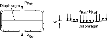
Fig 13. Diaphragm
Comparing table of diaphragm sensor types
Here's a simplified comparison table of different types of diaphragm sensors commonly used for pressure measurement:
Table 3. Comparing table
| Diaphragm Sensor Type | Description | Advantages | Limitations | Applications |
| Metal Diaphragm Sensor | Diaphragm made of metal (e.g., stainless steel) | Durable, resistant to harsh environments | Limited sensitivity, less suitable for low pressures | Industrial processes, automotive |
| Silicon Diaphragm Sensor | Diaphragm made of silicon | High sensitivity, accurate, suitable for low pressures | Sensitive to overpressure, higher cost | Medical devices, microelectromechanical systems (MEMS) |
| Elastomer Diaphragm Sensor | Diaphragm made of rubber or elastomers | Chemical resistance, suitable for corrosive media | Limited pressure range, lower accuracy | Chemical industry, hygienic applications |
| Ceramic Diaphragm Sensor | Diaphragm made of ceramics | High-temperature and high-pressure resistance | Brittle material, lower sensitivity | Oil and gas industry, heavy-duty applications |
| Capacitive Diaphragm Sensor | Diaphragm forms one plate of a capacitive element | High sensitivity, suitable for accurate measurements | Susceptible to environmental factors, complex electronics | Medical devices, aerospace |
| Piezoelectric Diaphragm Sensor | Diaphragm incorporates piezoelectric material | Fast response, suitable for dynamic measurements | Limited pressure range, lower accuracy | Vibration monitoring, impact testing |
| Optical Diaphragm Sensor | Diaphragm's deformation affects light transmission or reflection | Non-electrical, immune to electromagnetic interference | Limited pressure range, sensitivity to optical conditions | Medical imaging, research applications |
Keep in mind that this table provides a general overview and might not encompass all specific advantages, limitations, and applications for each diaphragm sensor type. The choice of diaphragm sensor type depends on factors such as pressure range, accuracy requirements, compatibility with media, and the specific conditions of the application.
Where can use the diaphragm sensor?
Diaphragm sensors are versatile devices that can be used in a wide range of industries and applications where pressure measurement is crucial. They are particularly suitable for applications that require accurate and reliable pressure readings, especially in challenging environments. Here are some common areas where diaphragm sensors find use:
- Industrial Automation: Diaphragm sensors are extensively used in industrial processes to monitor and control pressures in manufacturing, chemical processing, food and beverage production, and more.
- Aerospace and Aviation: These sensors are used in aircraft and spacecraft for monitoring cabin pressure, hydraulic systems, fuel systems, and other critical components.
- Automotive: Diaphragm sensors are found in automotive applications to measure tire pressure, fuel pressure, oil pressure, and other fluid pressures within the vehicle.
- Medical Devices: They are used in medical equipment such as anesthesia machines, ventilators, blood pressure monitors, and dialysis machines.
- HVAC Systems: Heating, ventilation, and air conditioning systems use diaphragm sensors to monitor pressures in refrigeration circuits, air ducts, and fluid systems.
- Hydraulic Systems: Diaphragm sensors are employed in hydraulic systems for machinery, vehicles, and equipment to monitor fluid pressures.
- Pneumatic Systems: They are used in pneumatic systems to measure air pressure in tools, machines, and industrial processes.
- Laboratory and Research: Diaphragm sensors are used in laboratory setups for pressure measurements in experiments and research, as well as in scientific instruments.
- Oil and Gas Industry: Diaphragm sensors find applications in the oil and gas sector for monitoring pressures in pipelines, wells, and various equipment.
- Water Treatment and Distribution: They are used in water treatment plants and distribution systems to monitor water pressures and fluid levels.
- Process Control: Diaphragm sensors play a crucial role in process control systems across various industries to maintain optimal pressure conditions.
- Environmental Monitoring: They are used for atmospheric pressure measurements in meteorology and weather stations.
- Food and Beverage Industry: Diaphragm sensors are used in food and beverage processing to monitor pressures in production lines and equipment.
- Semiconductor Manufacturing: They are used in semiconductor fabrication and cleanroom environments to monitor gas delivery and pressure control.
- Energy Production: Diaphragm sensors are employed in power generation plants to monitor steam pressure, coolant pressure, and other critical parameters.
- Fire Protection Systems: They are used in fire sprinkler systems to monitor water pressure and ensure effective fire suppression.
- Quality Control: Diaphragm sensors are used in various manufacturing processes to ensure consistent pressure levels and product quality.
These applications demonstrate the diverse utility of diaphragm sensors across a range of industries where accurate pressure measurements are essential for safety, efficiency, and process control.
What are the diaphragm sensor limitations?
Diaphragm sensors offer many advantages, but like any technology, they also come with certain limitations. It's important to consider these limitations when selecting and using diaphragm sensors for specific applications. Here are some common limitations of diaphragm sensors:
- Pressure Range: Diaphragm sensors have specific pressure ranges they are designed to handle. Using them beyond their specified range can lead to inaccurate measurements or sensor damage.
- Overpressure Sensitivity: Sudden pressure spikes or overpressure situations can damage the diaphragm or strain gauges, affecting sensor performance.
- Temperature Sensitivity: Extreme temperatures can influence the accuracy of diaphragm sensors due to changes in material properties, thermal expansion, and effects on electronic components.
- Environmental Factors: Factors such as humidity, moisture, dust, and chemical exposure can impact the sensor's performance and lifespan.
- Non-Linearity: Diaphragm sensors might exhibit non-linear behavior, particularly at the extreme ends of their pressure range. Linearization techniques are often required for high-accuracy applications.
- Hysteresis: Some diaphragm sensors might display hysteresis, where their output readings differ for pressure increases and decrease at the same point. This can affect measurement precision.
- Vibration and Shock Sensitivity: Diaphragm sensors can be sensitive to mechanical vibrations and shocks, leading to fluctuations in readings.
- Response Time: The mechanical deformation of the diaphragm might result in slower response times compared to some other types of pressure sensors.
- Fluid Compatibility: The material of the diaphragm must be compatible with the medium being measured to prevent corrosion, contamination, or degradation.
- Calibration and Drift: Diaphragm sensors require periodic calibration to maintain accuracy. Over time, drift can occur, necessitating recalibration.
- Cost: Depending on the application's requirements, diaphragm sensors can be more expensive than some other types of pressure sensors.
- Electronics Complexity: Diaphragm sensors require signal conditioning, amplification, and sometimes digital conversion, which can introduce complexities in terms of electronics design.
- Mechanical Wear: The repeated deformation of the diaphragm over time can lead to mechanical wear and affect long-term accuracy.
- Size and Bulk: Diaphragm sensors can be larger and less compact compared to certain other types of pressure sensors.
- Limited Digital Output: Some diaphragm sensors might not provide direct digital output, requiring additional signal conversion and processing.
- Health and Safety Concerns: Depending on the application, materials used, or the medium being measured, diaphragm sensors might need to meet specific safety and regulatory standards.
While diaphragm sensors are suitable for a wide range of applications, it's crucial to assess their limitations in the context of your specific requirements. In some cases, certain limitations might be mitigated through proper design, calibration, and selection of the appropriate sensor type.
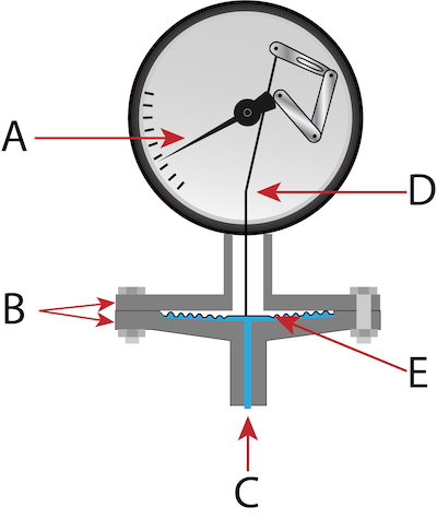
Fig 14. Diaphragm sensor
What are the advantages and disadvantages of using a diaphragm sensor?
Using diaphragm sensors offers several advantages and disadvantages that should be considered based on the specific requirements of your application. Here's a breakdown of the pros and cons of diaphragm sensors:
Advantages:
- Accuracy: Diaphragm sensors can provide accurate pressure measurements, especially when designed and calibrated properly.
- Wide Range of Applications: They can be used in a wide range of industries and applications, from industrial processes to medical devices.
- Compatibility: Diaphragm sensors can handle various types of media, including liquids and gases, depending on the diaphragm material.
- Reliability: With proper maintenance and calibration, diaphragm sensors can offer reliable and consistent measurements over time.
- Direct Pressure Measurement: Diaphragm sensors provide direct pressure measurement without the need for additional calculations or conversions.
- Rugged Construction: Depending on the design, diaphragm sensors can withstand harsh conditions, making them suitable for demanding environments.
- Dynamic Response: Diaphragm sensors can respond quickly to changes in pressure, making them suitable for dynamic applications.
- Compact Size: Many diaphragm sensors are compact and can be integrated into tight spaces or systems.
- Low Power Consumption: Depending on the design, diaphragm sensors might have low power requirements, making them suitable for battery-operated devices.
- Longevity: With proper care, diaphragm sensors can have a long operational lifespan.
Disadvantages:
- Temperature Sensitivity: Diaphragm sensors can be sensitive to temperature changes, which can affect their accuracy.
- Non-Linearity: They might exhibit non-linear behavior, particularly at the extreme ends of their pressure range, requiring additional calibration or linearization.
- Vibration and Shock Sensitivity: Diaphragm sensors can be affected by vibrations and shocks, leading to fluctuations in readings.
- Overpressure Limitation: Sudden overpressure events can damage the diaphragm or strain gauges and affect sensor accuracy.
- Response Time: Mechanical deformation of the diaphragm can result in slower response times compared to some other pressure-sensing technologies.
- Environmental Influences: Factors like humidity, moisture, dust, and chemicals can impact the sensor's performance.
- Complex Electronics: Signal conditioning and amplification electronics are required, which can introduce complexity to the system.
- Calibration Requirement: Diaphragm sensors need periodic calibration to maintain their accuracy.
- Cost: Depending on the application's requirements, diaphragm sensors can be more expensive than some other pressure-sensing methods.
- Limited Digital Output: Some diaphragm sensors might not provide direct digital output, requiring additional signal conversion and processing.
- Size and Bulk: Diaphragm sensors can be larger and less compact compared to certain other pressure sensors.
Considering these advantages and disadvantages will help you make an informed decision when selecting diaphragm sensors for your specific pressure measurement needs. It's important to evaluate these factors based on the application's requirements, accuracy demands, environmental conditions, and budget considerations.
Conclusion
In conclusion, the research on pressure measurement techniques, focusing on manometers and diaphragm sensors, provides a comprehensive understanding of these methods' principles, types, construction, applications, advantages, and limitations.
Manometers, as direct pressure measurement devices, come in various types such as U-tube, well-type, and inclined manometers. They rely on the balance between the pressure of the fluid column and an applied force, enabling accurate pressure readings. Manometers find applications in diverse industries including fluid dynamics research, medical devices, and industrial processes. However, they have limitations such as limited pressure range, fluid compatibility concerns, and the need for manual readings.
Bourdon tubes, a type of manometer, offer a mechanical means of pressure measurement by utilizing the elastic deformation of a curved tube. They are widely used due to their simplicity, durability, and suitability for various pressure ranges. Different types of Bourdon tubes cater to specific applications, ranging from low pressures to high pressures in different environments. Despite their advantages, they also have limitations like non-linearity, temperature sensitivity, and mechanical wear.
Diaphragm sensors, on the other hand, present a versatile electronic approach to pressure measurement. They employ flexible diaphragms made of materials like metal, silicon, or elastomers to convert pressure into electrical signals. These sensors are accurate, compatible with diverse media, and find use in industries ranging from automotive to medical devices. However, they are sensitive to factors like temperature changes, and vibrations, and require signal conditioning.
Understanding the strengths and weaknesses of these pressure measurement techniques is crucial for selecting the most appropriate method for specific applications. Manometers offer simplicity and direct measurement, while diaphragm sensors provide electronic precision. Both methods play essential roles in industries where accurate pressure measurement is pivotal for safety, control, and efficiency. By considering the nuances of these techniques, professionals can make informed decisions to ensure reliable pressure measurements in various contexts.
To recap
1. What is pressure measurement?
Pressure measurement involves quantifying the force exerted by a fluid (liquid or gas) on a surface. It's crucial for various applications to monitor and control processes accurately.
2. What are manometers used for?
Manometers are used to measure fluid pressure levels in various systems, such as industrial processes, medical devices, and scientific research.
3. How do manometers work?
Manometers work on the principle of balancing the pressure of a fluid column with an applied force, allowing direct visual measurement of pressure.
4. What are the types of manometers?
Types of manometers include U-tube, well-type, and inclined manometers, each with specific design variations and applications.
5. What is a Bourdon tube?
A Bourdon tube is a curved, elastic tube that deforms under pressure. It's commonly used as a pressure-sensing element in manometers and gauges.
6. How does a Bourdon tube work?
Bourdon tubes work by flexing when pressure is applied, causing the tube to straighten. This motion is converted into a readable measurement on a gauge.
7. What are the advantages of using a diaphragm sensor?
Diaphragm sensors offer accuracy, reliability, compatibility with various media, and the ability to measure dynamic pressures. They're used in industries like automotive, medical, and HVAC.
8. What is the purpose of a strain gauge in a diaphragm sensor?
Strain gauges on a diaphragm sensor measure the deformation of the diaphragm due to pressure changes. Changes in the resistance of the strain gauge indicate pressure variations.
9. Are diaphragm sensors suitable for high-pressure applications?
Yes, diaphragm sensors can be designed for high-pressure applications using robust diaphragm materials and reinforced construction.
10. What are the limitations of diaphragm sensors?
Diaphragm sensors can be sensitive to temperature changes, vibration, and shock. They might also exhibit non-linearity and require periodic calibration.
11. Which applications benefit from diaphragm sensors?
Diaphragm sensors are used in a wide range of applications, including industrial automation, medical devices, aerospace, HVAC systems, and more.
12. Are diaphragm sensors more accurate than manometers?
Both diaphragm sensors and manometers can offer accuracy, but the choice depends on the specific requirements of the application and the level of precision needed.
13. Can I use a diaphragm sensor for both liquids and gases?
Yes, diaphragm sensors can be designed for measuring both liquids and gases by selecting appropriate diaphragm materials and configurations.
14. Do manometers require power for operation?
No, most traditional manometers do not require external power for operation. They rely on the balance of fluid pressure and gravity.
15. Are manometers suitable for remote monitoring?
Manometers with direct visual readings might not be ideal for remote monitoring. However, modern electronic pressure sensors inspired by the manometer principle can provide remote monitoring capabilities.
References
http://ecoursesonline.iasri.res.in/mod/resource/view.php?id=3597
https://damatajhiz.com/en/products/7531/beta-manometer-thermometer
https://www.chsales.com.au/product-group/8516-u-tube-manometer/category/1624-gas
https://instrumentationtools.com/diaphragm-pressure-sensors/
https://tameson.com/pages/pressure-gauge-diaphragm
Recent Posts
-

Booster Pump Troubleshooting and Maintenance: How to Fix and Prevent Common Issues
1. Introduction Imagine turning on your faucet only to be greeted with a weak trickle of water when …22nd Apr 2025 -

Energy-Efficient Booster Pumps: Selection and Tips for Maximizing Performance
1. Introduction Imagine never having to deal with fluctuating water pressure, noisy pumps, or skyroc …19th Apr 2025 -

Booster Pumps for Sustainable Water Systems: Irrigation and Rainwater Harvesting Solutions
1. Introduction Water scarcity is no longer a distant threat—it’s a reality affecti …16th Apr 2025