Datexel
Modbus RTU/ASCII Device with Strain Gauge Input 4 or 6 Wires - DAT3025
- SKU:
- DAT3025 Series
- Weight:
- 90.00 Grams
Description
Product Overview
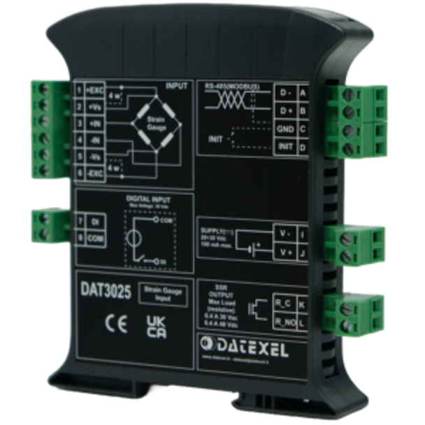
The DAT3025 is a versatile and reliable device designed for acquiring analog voltage signals from a 4 or 6 wire bridge transducer. It provides a configurable excitation voltage of either 5V or 10V, making it suitable for various applications. The data is transmitted using the MODBUS RTU/MODBUS ASCII protocols over an RS-485 network, ensuring robust and flexible communication. For users requiring an alternative interface, a model with RS-232 is also available upon request.
The DAT3025 includes a programmable SSR alarm threshold, allowing users to set maximum or minimum alarms according to their specific needs. Additionally, the device features a digital input for TARE operations, which can be controlled by a PLC. Configuration of the module is easily managed via the Modbus_3000_10000 software, making it user-friendly and adaptable to various industrial environments.
Please note that the product photo may not accurately represent the actual item. Always refer to the datasheet during installation to ensure proper setup and compliance with safety standards.
Key Features
- Modbus Server Device: Operates on RS-485, providing reliable data communication.
- Protocol Support: Compatible with Modbus RTU and Modbus ASCII protocols, offering flexibility in communication.
- Strain Gauge Input: Supports both 4 and 6 wires configurations, accommodating various types of transducers.
- Configurable Bridge Power Supply: Offers selectable excitation voltages of 5V or 10V, suitable for different transducer requirements.
- SSR Configurable Alarm: Programmable alarm threshold for precise monitoring and control.
- Remote Configuration: Easily configurable via Modbus_3000_10000 software, enhancing user convenience.
- High Galvanic Isolation: 1500 Vac 3-way isolation ensures safe operation and eliminates ground loop issues.
- LED Indicators: Front panel LEDs for power, communication, and alarm status monitoring.
- Removable Screw Terminals: Simplifies installation and maintenance.
- High Accuracy: Ensures precise data acquisition and processing.
- CE/UKCA Compliance: Certified for use in industrial environments.
Certifications
The DAT3025 is designed to meet rigorous industry standards, ensuring reliable performance in various environments:
- EMC Compliance: EN 61000-6-2 (Immunity) and EN 61000-6-4 (Emission) for industrial environments.
- UKCA Certification: Complies with BS EN 61000-6-2 and BS EN 61000-6-4 standards.
Input and Output Specifications
Digital Input (TARE)
- Voltage Range: 0-3V (OFF), 10-30V (ON)
- Input Impedance: 4.7 kOhm
SSR Output
- Contact Type: SPST – Normally Open
- Max Voltage: 48 VDC / 30 VAC
- Max Current: 0.4 A
Communication Capabilities
- Transmission Type: Asynchronous serial data transmission.
- Baud Rate: Up to 115.2 Kbps.
- Maximum Distance: 1.2 km.
- Supported Protocols: Modbus RTU / Modbus ASCII.
- Interface Options: RS485 (standard) or RS232 (optional).
Power Supply and Consumption
- Voltage Range: 20-30 VDC.
- Protection: Reverse polarity protection up to 60 VDC.
- Typical Consumption: 90 mA at 24 VDC.
- Maximum Consumption: 100 mA at 20 VDC.
Environmental Conditions
- Operating Temperature: -10°C to +60°C.
- Storage Temperature: -40°C to +85°C.
- Humidity: 0-90% (non-condensing).
- Maximum Altitude: 2000 meters above sea level.
- Installation: Indoor, Category II, Pollution Degree 2.
Mechanical Specifications
- Material: Self-extinguishing plastic with IP20 rating.
- Wiring Support: For wires with a diameter of 0.8 to 2.1 mm² (AWG 14-18).
- Tightening Torque: 0.5 Nm.
- Mounting: Compatible with EN-50022 DIN rail standard.
- Weight: Approximately 145 grams.
Installation Instructions
To ensure optimal performance and longevity of the DAT3025, adhere to the following installation guidelines:
- Mount the device vertically on a DIN rail, ensuring adequate spacing (at least 10 mm if UL certification is required, 5 mm if not).
- Do not obstruct the ventilation slots with ducts or other objects.
- Avoid mounting the device above heat-generating equipment. It is recommended to position the device in the lower part of the installation, whether it is a panel or cabinet.
- Install the device in a vibration-free location.
- Use shielded cables for connections and avoid routing wiring near power signal cables.
LED Signaling Guide
Power (PWR)
- Green ON: Device powered.
- Green OFF: Device not powered.
- Green BLINK: Data reception in progress.
Transmission (TX)
- Red OFF: No transmission in progress.
- Red BLINK: Data transmission in progress.
Status (STS)
- Yellow OFF: Device operating correctly.
- Yellow ON: Tare in progress or Digital Input ON.
Alarm/Output
- Red OFF: Threshold alarm not active, Digital Output OFF.
- Red ON: Threshold alarm active, Digital Output ON.
- Red BLINK: Watch-Dog Alarm or INIT Mode in progress.
Disposal Information
The DAT3025 must be disposed of in accordance with local electronic waste regulations. It should not be treated as household waste. Please contact your local waste management authority or the supplier for proper disposal methods.
Documents
You may want to read this product's catalog. If so, please click to view the DatexelDAT3025 Series datasheet.Additional Information
Modbus Server Device: |
RS-485. |
Protocols: |
Modbus RTU/ASCII. |
Strain Gauge Input: |
4 or 6 wires. |
Bridge Power Supply: |
5V or 10V. |
SSR Alarm: |
Configurable. |
Remote Configuration: |
Supported via software. |
Isolation: |
1500 Vac. |
LED Indicators: |
For power, communication, and alarms. |
Power Supply Voltage: |
20-30 VDC. |
Mounting: |
DIN rail, EN-50022 standard. |
Weight: |
145 grams. |


