Description
Danfoss pressure switch KP15
Dual pressure, high quality, SPDT contact function
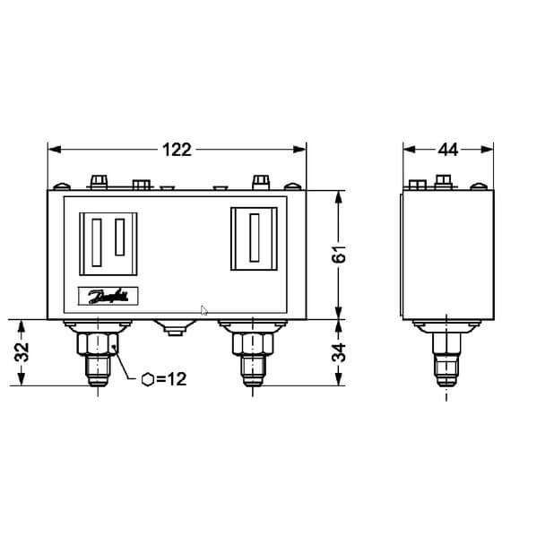
KP15 Danfoss dual pressure switch is designed for use as a pump guard to control and protect supply water pumps. It combines the functions of a pressure switch and a flow monitoring device. The left-hand pressure bellows control the pump pressure. The right-hand bellows cut out the pump if the suction pressure is too low. In this way the pump is protected from running dry and consequent bearing damage.
Danfoss KP15 pressure switch has several codes, each with their own properties. The most popular codes of this pressure switch are:
- 060-124166: with Auto reset on both low and high pressure side, and flare connection
- 060-124366: with Auto reset on low pressure side and manual (max.) reset on high pressure side, and flare connection
As a quick report, this pressure switch provides:
- Ultra-short bounce time thanks to snap action function (reduces wear to a minimum and increases reliability)
- Manual trip function (electrical contact function can be tested without the use of tools)
- Vibration and shock resistant
- Compact design
- Fully welded bellows element
- High reliability both electrically and mechanically
Body
In KP15 pressure switches, parts that are in contact with the medium are made from Tin bronze and Nickel plated free cutting steel.
Enclosure IP30 is obtained when the units without top cover are mounted on a flat surface or bracket. Enclosure IP44 is obtained when the units with top cover are mounted on a flat surface or bracket. The bracket must be fixed to the unit so that all unused holes are covered. And IP55 is obtained when the KP pressure switches are mounted in an IP55 enclosure. This enclosure has to be ordered separately.
Reset function
As this pressure switch is dual pressure type, it has two reset functions. Different codes of KP15 have their own specific reset function types, which are combinations of auto and manual. Four codes of KP15 have conv. reset functions in their both low and high pressure side, which means you can optionally set them on auto or manual. although, reset functions of the most common codes of this pressure switch are:
- 060-124166: Auto reset on both low and high pressure sides
- 060-124366: Auto reset on low pressure side and manual (max.) on high pressure side
Set up ranges
In dual pressure switches, you should set up the ranges twice, once for low pressure side and the other time for the high pressure side.
For auto reset on the low pressure side, you should first set the LP start pressure on the "CUT-IN" scale (range scale). This pressure should be within the regulation pressure range. then Set the LP differential (Δp) on the "DIFF" scale. The LP stop or "CUT-OUT" pressure is the LP start pressure minus the differential. take notice that the LP stop pressure must be above absolute vacuum (-1 bar).
For auto reset on the high pressure side, Set the HP pressure on the “CUT-OUT” scale, which also should be within the regulating pressure range. Then Set the HP differential (Δp) on the “DIFF” scale. The HP start or "CUT-IN" pressure is the HP stop pressure minus the differential.
Start and stop pressures for both the LP and HP sides of the system should always be checked with an accurate pressure gauge.
For the pressure switches with manual reset, set the stop pressure on “CUT-OUT” scale (range scale). The selected pressure should be within the regulating pressure range. Low pressure side can be manually reset when the pressure is equal to the stop pressure plus the differential (Δp). High pressure side can be manually reset when the pressure is equal to the stop pressure minus the differential.
Regulating pressure range and differential (Δp) differs from one KP15 code to another. For both 060-124166 and 060-124366 common codes, this values are as below:
- Regulating range: -0.2 ... 7.5 bar for low pressure side and 8 ... 32 bar for high pressure side
- differential (Δp): 0.7 ... 4.0 bar for low pressure side and 4 bar for high pressure side
Pressure connection
There are two pressure connection types for KP15 different codes. But the pressure connections for the two common codes are male ¼ in. flare, with the DIN 8906 standard.
Electrical connection
The electrical connection of KP15 pressure switches is rubber cable gland, which can be used for cables with 6 to 14 mm diameter.
Design
Here is the schematic picture of KP15:
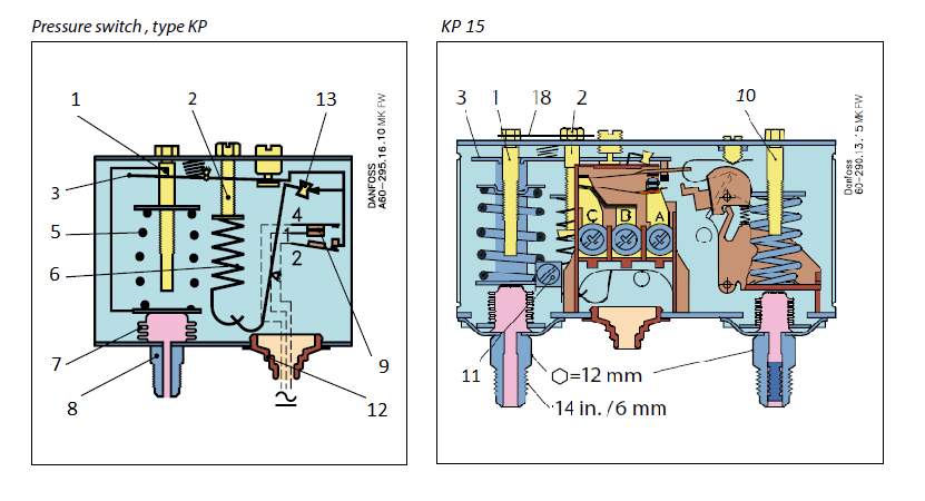
1. Low pressure (LP) setting spindle
2. Differential setting spindle, (LP)
3. Main arm
5. Main spring
6. Differential spring
7. Bellows
8. HP connection
9. Earth terminal
10. High pressure (HP) setting spindle
11. Earth terminal
12. Cable entry
13. Tumbler
18. Locking plate
Temperature
Different permissible temperature conditions are defined for using this product:
- Ambient temperature: -40 … 65°C
- Medium temperature: -50 … 100°C
Industries / applications
- protecting supply water pumps
Series Information
KP Series
Pressure switches for commercial refrigeration applications
Danfoss KP series pressure switches are specialized for use in refrigeration and air conditioning systems to make protection against excessively low suction pressure or excessively high discharge pressure. The switches are also used for starting and stopping refrigeration compressors and fans on air-cooled condensers.
With the KP pressure switches you get great reliability and long service life due to the snap-action function ensuring ultra-short bounce times. The KP pressure switch is available with IP30, IP44 and IP55 enclosures for appropriate protection based on the application.
KP series main features
• Ultimate installation protection against freezing
• Small dimensions
• Space-saving, easy to install
• Shock and impact resistant
• Ultra-short bounce time
Documents
Additional Information
Pressure range category: |
Dual pressure |
LP regulating range: |
-0.2 ... 7.5 bar / -0.9 ... 7.0 bar |
HP regulating range: |
8 ... 32 bar |
LP Differential (∆p): |
0.7 ... 4.0 bar / 0.7 bar |
HP Differential (∆p): |
4 bar |
Pressure sensing element: |
Bellows |
Contact Function: |
SPDT + LP signal / SPDT + LP and HP signal |
Reset: |
Auto / Manual (max.) / Manual (min.) / Conv. |
Pressure connection: |
¼ in. 6 mm Flare / ¼ in. ODF solder |
Electrical connection: |
Rubber cable gland |
Electrical connection size: |
6 ... 14 mm |
Enclosure rating IP: |
IP30 / IP44 / IP55 |
LP Max. Working Pressure: |
17 bar |
HP Max. Working Pressure: |
35 bar |
Ambient temperature: |
-40 ... 65 °C |
Media temperature: |
-50 ... 100 °C |


